12: BOOLEAN COMPUTATION INSTRUCTIONS
12-2 OPENNET CONTROLLER USER’S MANUAL
Valid Operands
For the valid operand number range, see page 6-2.
▲ Internal relays M0 through M2557 can be designated as D1. Special internal relays cannot be designated as D1.
When T (timer) or C (counter) is used as S1 or S2, the timer/counter current value is read out. When T (timer) or C
(counter) is used as D1, the data is written in as a preset value which can be 0 through 65535.
Since the Boolean computation instructions are executed in each scan while input is on, a pulse input from a SOTU or
SOTD instruction should be used as required.
Valid Data Types
When a bit operand such as I (input), Q (output), M (internal relay), or R (shift register) is designated as the source or des-
tination, 16 points (word data type) or 32 points (double-word data type) are used. When repeat is designated for a bit
operand, the quantity of operand bits increases in 16- or 32-point increments.
When a word operand such as T (timer), C (counter), D (data register), or L (link register) is designated as the source or
destination, 1 point (word data type) or 2 points (double-word data type) are used. When repeat is designated for a word
operand, the quantity of operand words increases in 1- or 2-point increments.
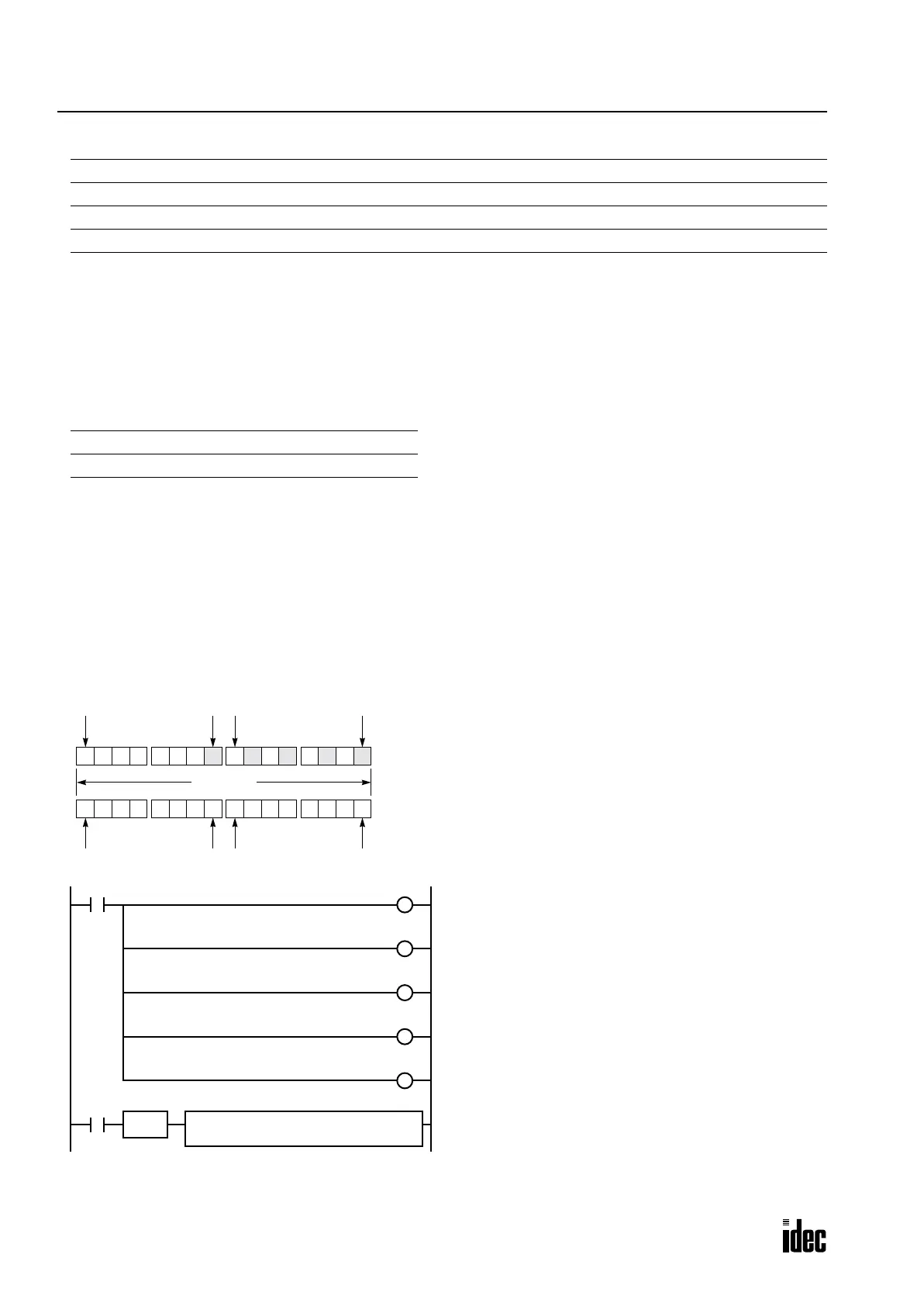
Example: XORW
To convert optional output status among a series of 10 output points, use the XORW instruction in combination with 10
internal relay points.
Operand Function I Q M R T C D L Constant Repeat
S1 (Source 1) Data for computation XXXXXXXX X 1-99
S2 (Source 2) Data for computation XXXXXXXX X 1-99
D1 (Destination 1) Destination to store results — X ▲ XXXXX — 1-99
W (word) I (integer) D (double word) L (long)
X — X —
M8120
Sixteen outputs Q0 through Q17 are assigned to 16
internal relays M0 through M17.
Five internal relays M0, M2, M4, M6, and M10 are set
by initialize pulse special internal relay M8120.
When input I1 is turned on, the XORW instruction is
executed to invert the status of outputs Q0, Q2, Q4, Q6,
and Q10.
0 0 00 0 0 1 10 0 1 0 1 0 1 0
Q0
Q7
Q10
Q17
16 points
This program will invert the status of the shaded outputs at the
left from on to off, and those not shaded from off to on.
REPS1 –
M0
S2 –
Q0
D1 –
Q0
SOTU
I1
M0M7M10M17
XORW(W)
M0
S
M2
S
M4
S
M6
S
M10
S
Phone: 800.894.0412 - Fax: 888.723.4773 - Web: www.clrwtr.com - Email: info@clrwtr.com

 Loading...

