20: PID INSTRUCTION
20-4 OPENNET CONTROLLER USER’S MANUAL
S1+3 Operation Mode
When the start input for the PID instruction is turned on, the CPU module checks the value stored in the data register des-
ignated by S1+3 and executes the selected operation. The selection cannot be changed while executing the PID instruction.
0: PID action
The PID action is executed according to the designated PID parameters such as proportional gain (S1+7), integral time
(S1+8), derivative time (S1+9), and control action (S2+0).
1: AT (auto tuning) + PID action
Auto tuning is first executed according to the designated AT parameters such as AT sampling period (S1+19), AT con-
trol period (S1+20), AT set point (S1+21), and AT output manipulated variable (S1+22). As a result of auto tuning, PID
parameters are determined such as proportional gain (S1+7), integral time (S1+8), derivative time (S1+9), and control
direction (S2+0), then PID action is executed according to the derived PID parameters.
2: AT (auto tuning)
Auto tuning is executed according to designated AT parameters to determine PID parameters such as proportional gain
(S1+7), integral time (S1+8), derivative time (S1+9), and control direction (S2+0); PID action is not executed.
S1+4 Linear Conversion
0: Disable linear conversion
Linear conversion is not executed. When the linear conversion is disabled (S1+4 set to 0), the analog input data (0
through 4000) from the analog I/O module is stored to the process variable (S4), and the same value is stored to the
process variable (S1+0) without conversion.
1: Enable linear conversion
The linear conversion function is useful for scaling the process variable to the actual measured value in engineering
units.
When the linear conversion is enabled (S1+4 set to 1), the analog input data (0 through 4000) from the analog I/O mod-
ule is linear-converted, and the result is stored to the process variable (S1+0). When using the linear conversion, set
proper values to the linear conversion maximum value (S1+5) and linear conversion minimum value (S1+6) to specify
the linear conversion output range. When using the linear conversion function in a temperature control application,
temperature values can be used to designate the set point (S3), high alarm value (S1+14), low alarm value (S1+15), and
AT set point (S1+21), and also to read the process variable (S1+0).
S1+5 Linear Conversion Maximum Value
When the linear conversion is enabled (S1+4 set to 1), set the linear conversion maximum value to the data register desig-
nated by S1+5. Valid values are –32768 through 32767, and the linear conversion maximum value must be larger than the
linear conversion minimum value (S1+6). Select an appropriate value for the linear conversion maximum value to repre-
sent the maximum value of the input signal to the analog I/O module.
When the linear conversion is disabled (S1+4 set to 0), you don’t have to set the linear conversion maximum value (S1+5).
S1+6 Linear Conversion Minimum Value
When the linear conversion is enabled (S1+4 set to 1), set the linear conversion minimum value to the data register desig-
nated by S1+6. Valid values are –32768 through 32767, and the linear conversion minimum value must be smaller than the
linear conversion maximum value (S1+5). Select an appropriate value for the linear conversion minimum value to repre-
sent the minimum value of the input signal to the analog I/O module.
When the linear conversion is disabled (S1+4 set to 0), you don’t have to set the linear conversion minimum value (S1+6).
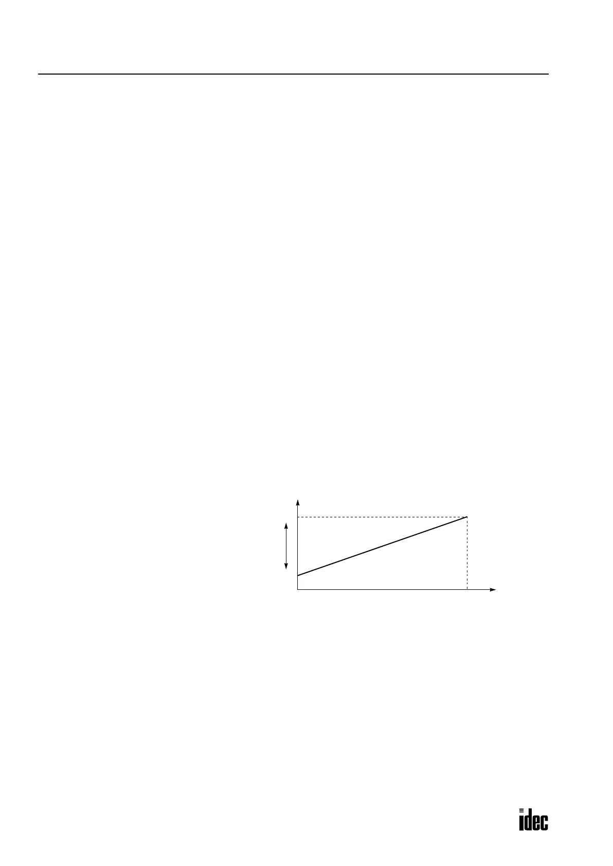
Linear Conversion Result
0
Analog Input Data
Linear Conversion Maximum Value (S1+5)
Linear Conversion Minimum Value (S1+6)
4000
Set point (S3), AT set point (S1+21), and process
variable (S1+0) must be within this range.
Phone: 800.894.0412 - Fax: 888.723.4773 - Web: www.clrwtr.com - Email: info@clrwtr.com

 Loading...

