26: LONWORKS INTERFACE MODULE
OPENNET CONTROLLER USER’S MANUAL 26-15
Neuron Chip I/O Pins and Status LEDs
Neuron Chip I/O pins and status LEDs are assigned as listed below:
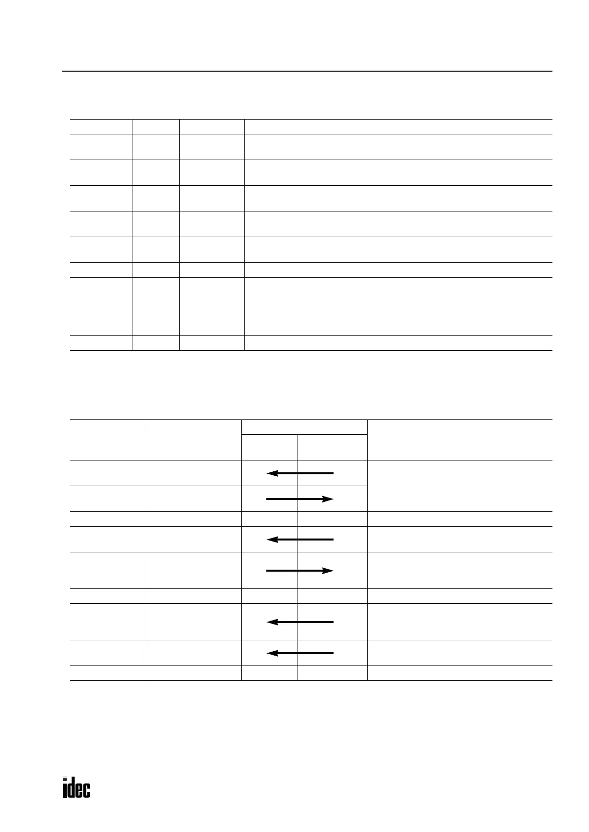
Registers
The
OpenNet Controller CPU module exchanges communication data through the registers in the LONWORKS interface
module. The register addresses are listed in the table below:
I/O Pin No. I/O Signal Name Description
0 Output RUN LED
Controls the RUN LED (green).
0: ON, 1: OFF
1 Output ERR LED
Controls the ERR LED (red).
0: ON, 1: OFF
2 Output I/O LED
Controls the I/O LED (red).
0: ON, 1: OFF
3 Input —
The IO.3 pin must be defied as an input when the application program is
modified by the user. See page 26-19.
4 Input RUN
Monitors the CPU module operating status.
0: CPU stopped, 1: CPU in operation
5 — unused
6 Output Failure
Error signal to the CPU
0: The Neuron Chip cannot write data to registers. When modifying the appli-
cation program, make sure to turn this pin to 0 when an unrecoverable
critical error occurs.
1: Normal operation
7-10 — unused
Address Name
Data Flow Direction
Description
CPU
Module
Interface
Module
C000h - C007h
Data register
(8 bytes)
Allocate network variables to these
addresses to exchange data between the
CPU and interface modules.
C008h - C00Fh
Data register
(8 bytes)
C010h - C011h reserved ——Do not write data into this area.
C012h Error data
Use this address to read error data from the
interface module.
C013h I/O counts
Use this address to store the byte counts of
transmit/receive data selected in WindLDR
Function Area Settings.
C014h - C017h reserved ——Do not write data into this area.
C018h Software version
Use this address to write the user applica-
tion software version number (use any num-
ber other than 00h).
C019h Expansion module ID
Use this address to write the user program
module ID (use a number 40h through 7Fh).
C01Ah - CFFFh reserved ——Do not write data into this area.
Phone: 800.894.0412 - Fax: 888.723.4773 - Web: www.clrwtr.com - Email: info@clrwtr.com

 Loading...

