2: MODULE SPECIFICATIONS
2-30 OPENNET CONTROLLER USER’S MANUAL
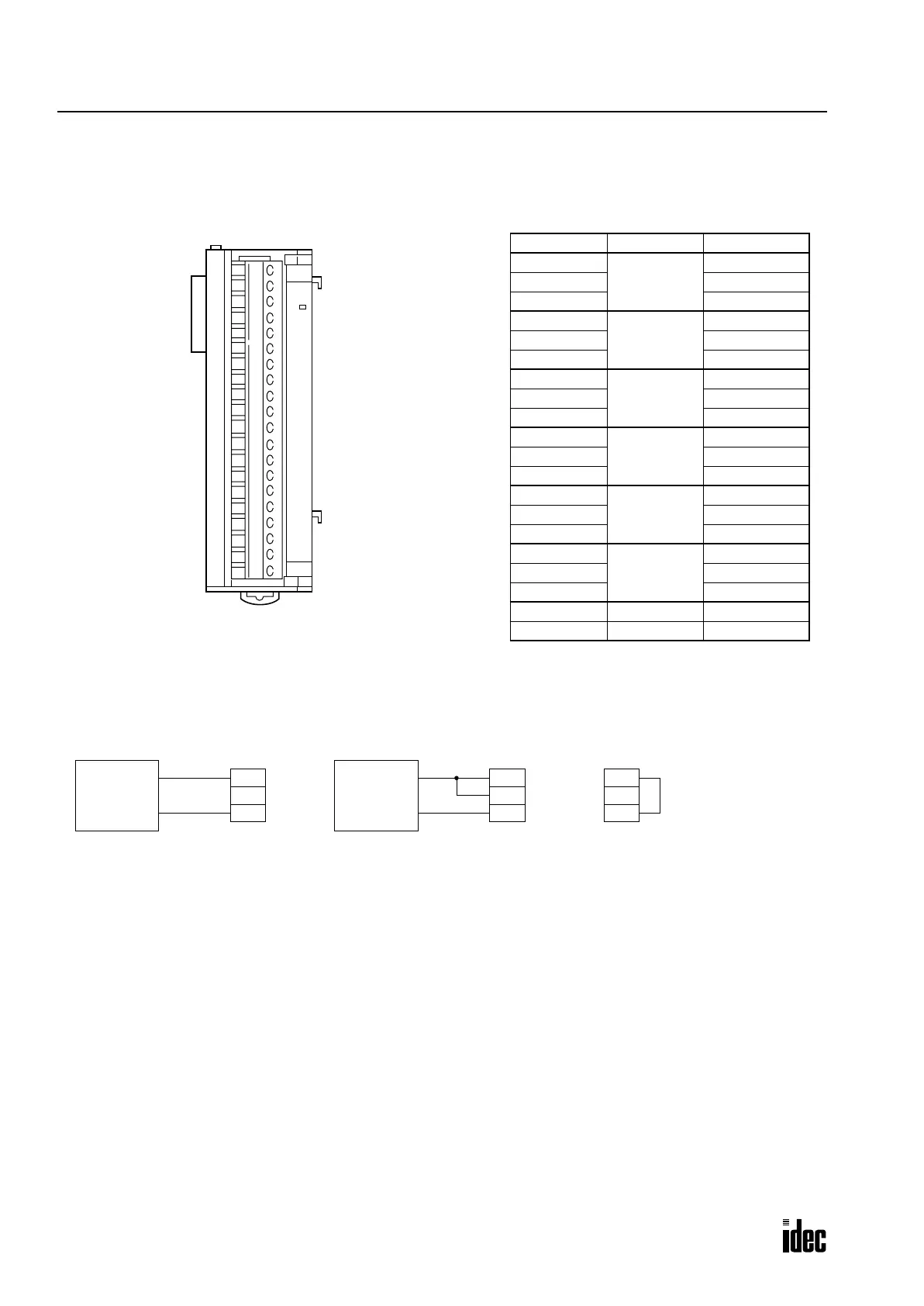
Analog Input Module Terminal Arrangement
FC3A-AD1261 (6-channel Analog Input Module) — Screw Terminal Type
Applicable Connector: SMSTB2.5/20-ST-5.08 (Phoenix Contact)
Wiring Diagram
Example: When converting an analog voltage input (0 to 10V, ±10V, 0 to 5V, or ±5V DC) using channel 4, connect the
signal to terminals 13 and 15. When the analog input module is the second functional module installed in the
OpenNet
Controller
system, the converted digital value is stored to link register L204. When connecting an analog current input (4
to 20 mA), connect terminals +I and +V together, and connect the input across terminals +I and COM as shown in the mid-
dle above.
For wiring schematic and precautions, see page 3-8.
Notes:
• Before mounting the analog input module, first set the rotary switch to meet the required analog input range. After setting
the rotary switch, power up the CPU and other modules.
• The COM (–V, –I) terminal of each channel is independent from each other.
• Connect the +V and COM terminals of unused channels together. Connecting these terminals together will reduce the AD
conversion time in the analog input module (by approximately 10% for every unused slot).
PCW
A/D
Terminal No. Channel Name
1
Channel 0
+V (voltage)
2 +I (current)
3 COM (–V, –I)
4
Channel 1
+V (voltage)
5 +I (current)
6 COM (–V, –I)
7
Channel 2
+V (voltage)
8 +I (current)
9 COM (–V, –I)
10
Channel 3
+V (voltage)
11 +I (current)
12 COM (–V, –I)
13
Channel 4
+V (voltage)
14 +I (current)
15 COM (–V, –I)
16
Channel 5
+V (voltage)
17 +I (current)
18 COM (–V, –I)
19 — NC
20 — NC
Voltage Input
Analog
(+)
(–)
+V
Voltage
Output
Device
Analog
Input
Module
+I
COM
0 to 10V, ±10V, 0 to 5V, ±5V
Current Input
Analog
(+)
(–)
+V
Current
Output
Device
Analog
Input
Module
+I
COM
4 to 20 mA
Unused Channel
+V
Analog
Input
Module
+I
COM
Connect +V and COM
terminals of unused
channels together.
Phone: 800.894.0412 - Fax: 888.723.4773 - Web: www.clrwtr.com - Email: info@clrwtr.com

 Loading...

