2: MODULE SPECIFICATIONS
OPENNET CONTROLLER USER’S MANUAL 2-33
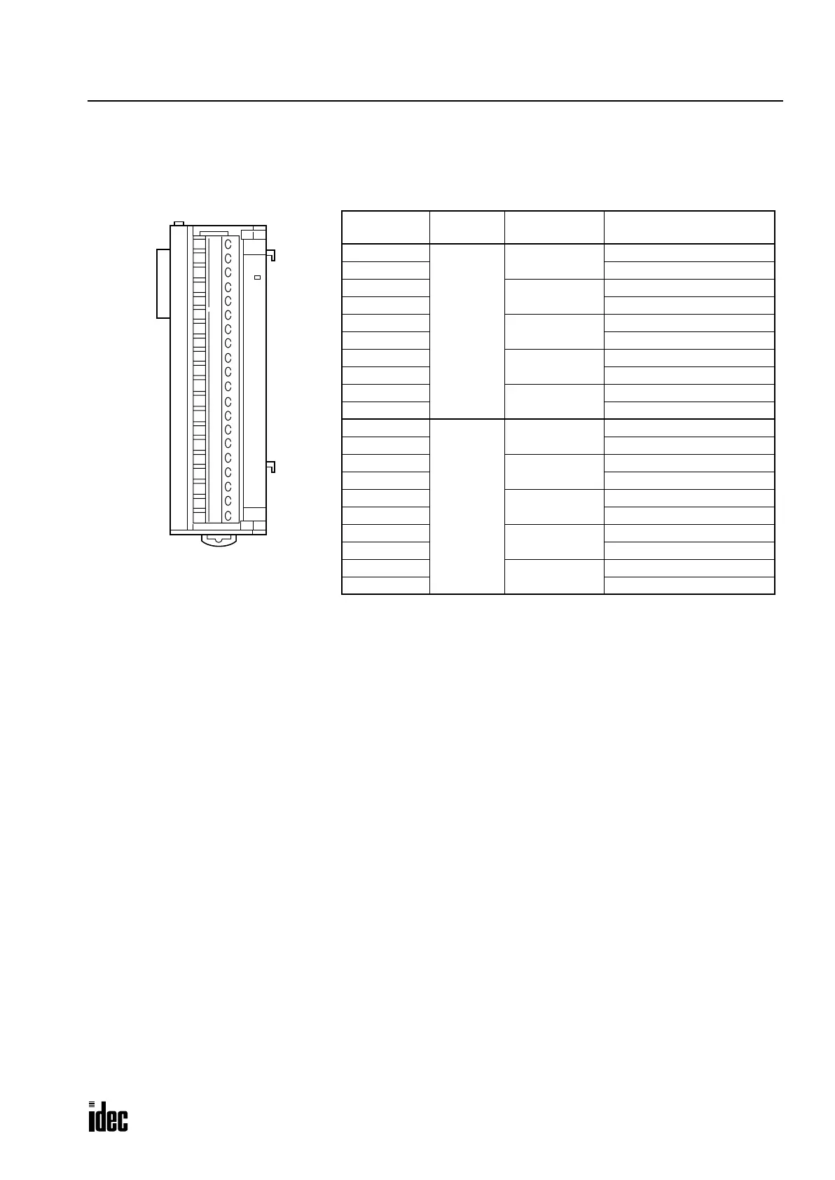
Analog Output Module Terminal Arrangement
FC3A-DA1221 (2-channel Analog Output Module) — Screw Terminal Type
Applicable Connector: SMSTB2.5/20-ST-5.08 (Phoenix Contact)
Wiring Example:
Suppose that an analog output module is the sixth functional module installed in the
OpenNet Controller system. To gener-
ate a 4V analog output voltage from channel 1 using the 0 to 5V output range, set the rotary switch to 2 and store a digital
value of 3200 to link register L601, which is assigned to channel 1 of the sixth functional module.
Because 5V × 3200/4000 = 4V, digital value 3200 is converted to an analog value of 4V and outputted to terminals 15 and
16 of the analog output module.
For wiring schematic and precautions, see page 3-8.
Notes:
• Before mounting the analog output module, first set the rotary switch to meet the required analog output range. After set-
ting the rotary switch, power up the CPU and other modules.
• The COM (GND) terminals of each channel are connected together internally.
D/A
PCW
Terminal No. Channel
Rotary Switch
Position
Name
1
Channel 0
0
Voltage output (0 to 10V)
2 COM (GND)
3
1
Voltage output (±10V)
4 COM (GND)
5
2
Voltage output (0 to 5V)
6 COM (GND)
7
3
Voltage output (±5V)
8 COM (GND)
9
4
Current output (4 to 20mA)
10 COM (GND)
11
Channel 1
0
Voltage output (0 to 10V)
12 COM (GND)
13
1
Voltage output (±10V)
14 COM (GND)
15
2
Voltage output (0 to 5V)
16 COM (GND)
17
3
Voltage output (±5V)
18 COM (GND)
19
4
Current output (4 to 20mA)
20 COM (GND)
Phone: 800.894.0412 - Fax: 888.723.4773 - Web: www.clrwtr.com - Email: info@clrwtr.com

 Loading...

