5: SPECIAL FUNCTIONS
5-8 OPENNET CONTROLLER USER’S MANUAL
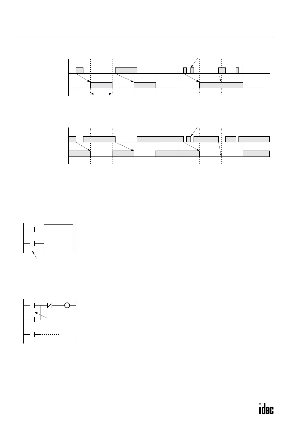
Catching Rising Edge of Input Pulse
Catching Falling Edge of Input Pulse
Note 1: When two or more pulses enter within one scan, subsequent pulses are ignored.
Note 2: The pulse entering at the timing shown above cannot be used as pulse inputs for counters and shift registers.
Example: Counting Catch Input Pulses
This example demonstrates a program to count short pulses using the catch input function.
Example: Maintaining Catch Input
When a catch input is received, the input relay assigned to a catch input is turned on for only one scan. This example dem-
onstrates a program to maintain a catch input status for more than one scan.
Note: To catch as short inputs as possible, select 0 msec in the Input Filter Time Selection field.
Actual Input
ON
OFF
Input Relay
ON
OFF
(I0 to I7)
Note 1
Note 2
END
Processed
One Scan
Actual Input
ON
OFF
Input Relay
ON
OFF
(I0 to I7)
Note 1
Note 2
END
Processed
CNT C2
100
I1
Reset
Pulse
I0
Designate input I1 as a catch input
Input I0 is used as a reset input for adding counter C2.
Input I1 is designated as a catch input using the Function Area Settings.
Counter C2 counts short-pulse inputs to input I1.
Note: When a catch input is used as a pulse input to a counter, the repeat cycle period of
the pulse inputs must be more than 2 scan times.
M0
I0
Input I0 is designated as a catch input using the Function Area Settings.
When input I0 is turned on, internal relay M0 is turned on, and M0 is maintained in the
self-holding circuit.
When NC input I1 is turned off, the self-holding circuit is unlatched, and M0 is turned off.
M0 is used as an input condition for the subsequent program instructions.
M0
I1 M0
Catch input
Phone: 800.894.0412 - Fax: 888.723.4773 - Web: www.clrwtr.com - Email: info@clrwtr.com

 Loading...

