HD2 Series Inverter Function Parameter List
-170-
HDIA terminal
switch-off delay
HDIB terminal
switch-on delay
HDIB terminal
switch-off delay
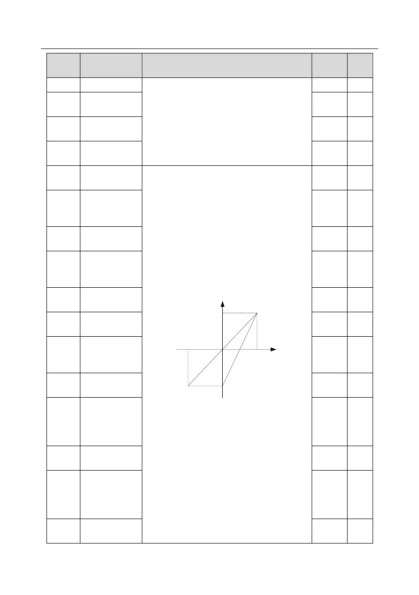
These function codes define the relation between
analog input voltage and corresponding set value
of analog input. When the analog input voltage
exceeds the range of max./min. input, the max.
input or min. input will be adopted during
calculation.
When analog input is current input, 0–20mA
current corresponds to 0–10V voltage.
In different applications, 100% of analog setting
corresponds to different nominal values.
The figure below illustrates several settings.
-100%
100%
Corresponding setting
AI
-10V
10V
20mA
0
AI2
AI1
Input filter time: Adjust the sensitivity of analog
input, increase this value properly can enhance
the anti-interference capacity of analog variables;
however, it will also degrade the sensitivity of
analog input.
Note: AI1 can support 0–10V/0–20mA input, when
AI1 selects 0–20mA input; the corresponding
voltage of 20mA is 10V; AI2 supports -10V–+10V
input.
Setting range of P05.24: 0.00V–P05.26
Setting range of P05.25: -300.0%–300.0%
Setting range of P05.26: P05.24–10.00V
Corresponding
setting of lower
limit of AI1
Corresponding
setting of upper
limit of AI1
Corresponding
setting of lower
limit of AI2
Intermediate
value 1 of AI2
Corresponding
setting of
intermediate
value 1 of AI2
Intermediate
value 2 of AI2
Corresponding
setting of
intermediate
value 2 of AI2