HD2 Series Inverter Function Parameter List
-174-
50: AI/AO detected OH pre-alarm
51: Stopped or running at zero speed
52: Disconnection detected in tension control
53: Roll diameter setting reached
54: Max. roll diameter reached
55: Min. roll diameter reached
56: Fire control mode enabled
57–63: Reserved
Output terminal
polarity selection
This parameter specifies the polarity of output
terminals.
When the bit is set to 0, input terminal polarity is
positive.
When the bit is set to 1 input terminal polarity is
negative.
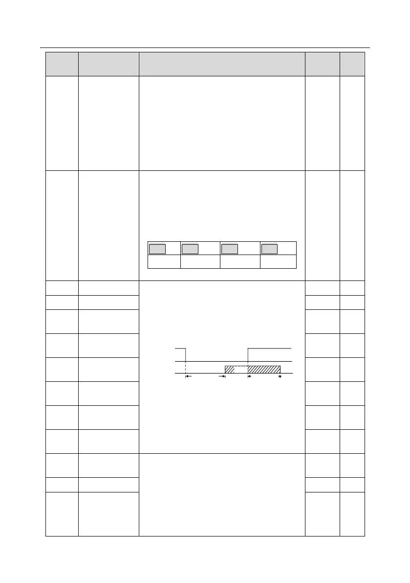
This function code defines the corresponding
delay of the level variation from switch-on to
switch-off.
Y electric level
Y valid
Invalid
Switch on
delay
invalid
Valid
Switch off
delay
Setting range: 0.000–50.000s
Note: P06.08 and P06.09 are valid only when
P06.00=1.
Relay RO1
switch-on delay
Relay RO1
switch-off delay
Relay RO2
switch-on delay
Relay RO2
switch-off delay
0: Running frequency (0–Max. output frequency)
1: Set frequency (0–Max. output frequency)
2: Ramp reference frequency (0–Max. output
frequency)
3: Rotational speed (0–Speed corresponding to
max. output frequency)
4: Output current (0–Twice the inverter rated
HDO high-speed
pulse output