Radar Field Analyser - RFA641 Edition Date: 28-Feb-18
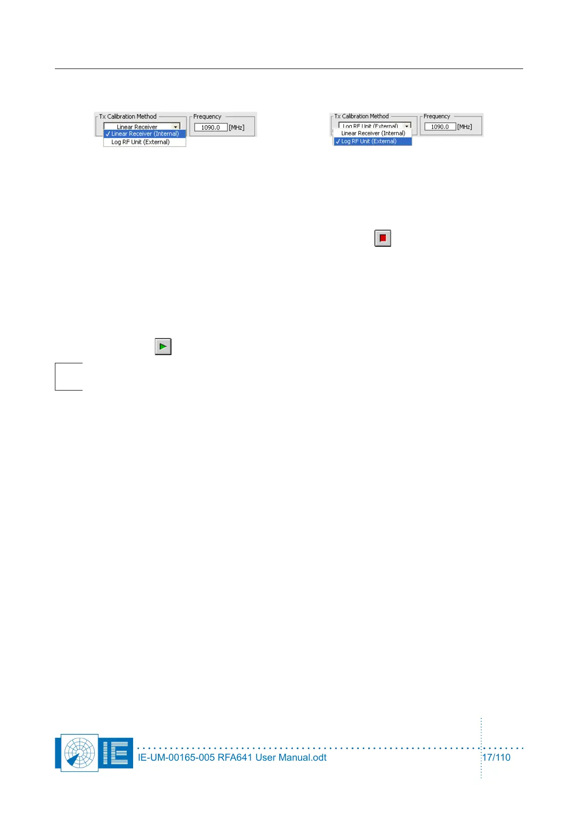
Choose the calibration method that you want to use by selecting Linear Receiver (Internal) or Log RF Unit
(External) and select the SSR Downlink frequency (1090 MHz) or the correct PSR frequency.
When the internal Tx Calibration method is used, the linear receiver will be used to perform VNA
measurements, this method is explained in section 2.2.2. . When the external Tx Calibration method is used,
the linear receiver will be used to perform the cable measurements and the log RF unit will be used to
perform the power measurements, this method is explained in section 2.2.3. .
In case you want to abort the test sequence, you can always hit the Abort button. It allows ending the
sequence at the end of the test that is being executed at the moment you pressed the button.
The two methods implemented are discussed in the next two paragraphs.
2.2.2. Internal Tx Calibration Method
When the internal Tx Calibration method is used, the linear receiver will be used to perform VNA
measurements.
1. Click the Start button to start the test sequence.
Note: The program will guide you through the successive steps and required connections
to perform the selftest.
2. First the noise level of the system is measured versus frequency. For this purpose the transmitter is
set to maximum power. While input and output are terminated, a frequency sweep over the full
RFA641 frequency range is performed to measure the systems noise level.
3. Then the Cable Test is performed. The internal electrical length must be measured first. The program
will ask you to connect the 0.5m cable between the attenuators at the Tx and Rx ports of the
RFA641.
Once the connection is made, click OK to continue the measurement. The electrical length is
measured by performing a frequency sweep. The slope of the phase change versus frequency is
determined. It is directly corresponding to the length of the cable.
Once the 0.5m cable length is determined, the program will ask you to replace the 0.5m cable by the
4m antenna cable. Again the VNA measurement is performed to measure the cable length. By
subtracting the internal electrical length, the cable length can be determined. The result is displayed
in the Cable Test section.
The error LED will be red in case the cable length reported is less than 3.5m or more than 4.5m, and
an error message is generated, e.g.: “Cable length = 4.7m ... outside 3.5m!!! ... 4.5m!!!”.
After the 4m cable sweep, the reference level for the selected frequency is measured. This is done
using a VNA sweep from 50 MHz below to 50 MHz above the selected selftest frequency. In this
step the VNA power is compared with a reference derived from file. The reference power is
subtracted from the measured value; this results in the power error vs. frequency being calculated.
4. Now the RFA Selftest program will ask you to insert the YIG filter in the loop. The YIG filters insertion
loss will be measured. A frequency sweep will be performed as well. This allows the selftest program
IE-UM-00165-005 RFA641 User Manual.odt 17/110