Radar Field Analyser - RFA641 Edition Date: 28-Feb-18
The calibration will now be executed.
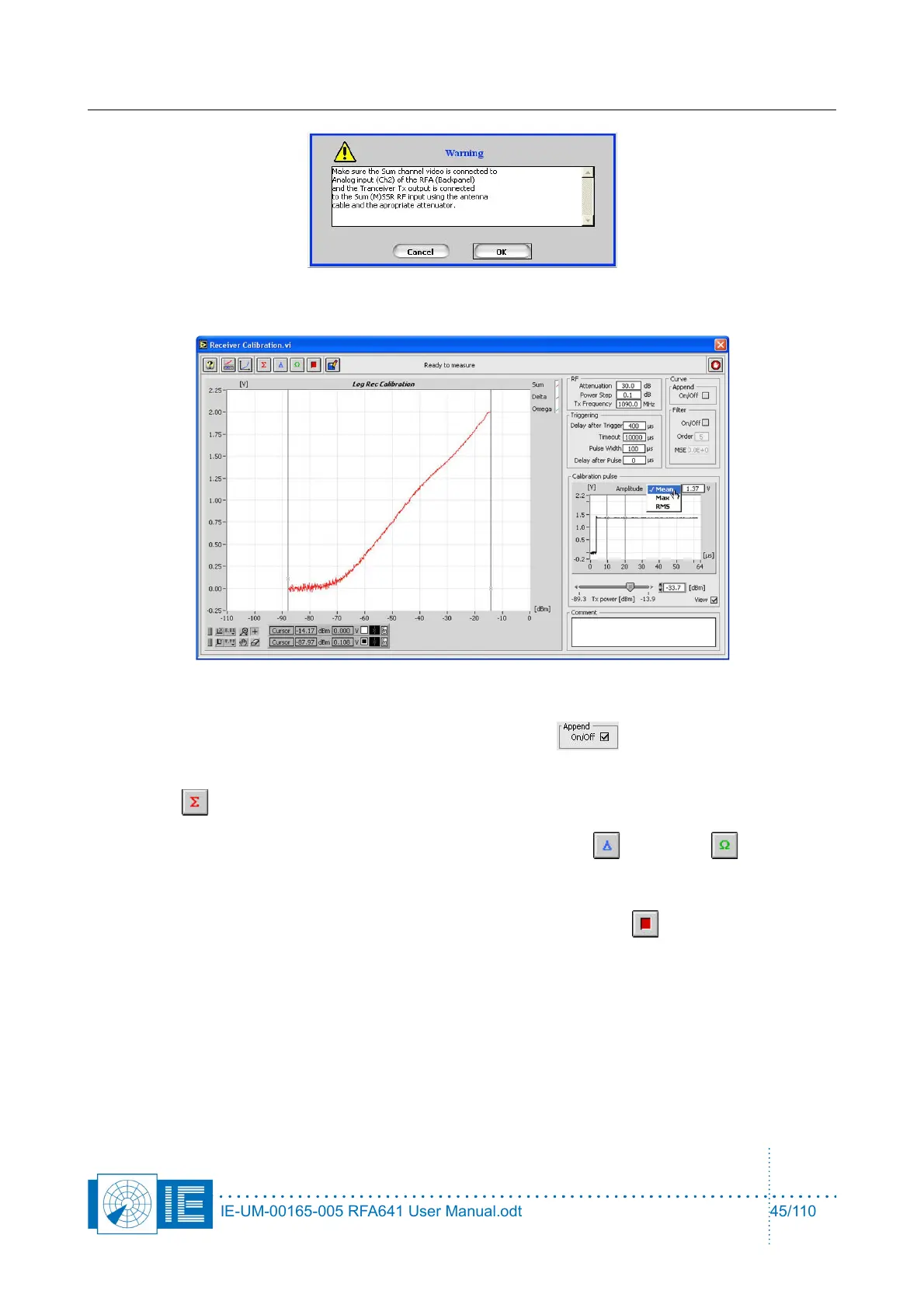
6. If the noise level of the receiver is not reached during the calibration, the receiver calibration
measurement can be performed in successive steps in order to increase the overall dynamic range
of the receiver measurement. To do this, check the Append button and insert an extra
attenuator after the first run.
Enter the correct new attenuation value into the Extra Attenuation parameter and again click the
Sum button. The software will append the two calibration curves to each other.
7. For MSSR stations: proceed with the measurements of the Delta and Omega channels.
Press the respective buttons on the software front panel, change the connections as described in the
pop-up window and repeat steps 4, 5 and 6.
8. A calibration procedure can always be interrupted by clicking the Stop button.
9. The user can select a filter option, so that the calibration curves are improved and spikes, due to the
operational use of the radar, are removed. To do this, check the Filter check box on the graph. The
filtering is done only for the part of the curves between the cursors. So move the left cursor
approximately to the noise floor intercept point before checking the filter box to reduce the curve
fitting oscillations. The filter consists of a median filter of order 1 followed by a polynomial fit
algorithm, from which the user can alter the default order of 5 to a higher value. The MSE indicator
shows the Mean Squared Error of the curve filtering.
IE-UM-00165-005 RFA641 User Manual.odt 45/110