Radar Field Analyser - RFA641 Edition Date: 28-Feb-18
4. RECEIVER MEASUREMENTS
4.1. Radar Rx Calibration
4.1.1. Theory
The RF Receiver is needed to convert the very low levels of RF available at the antenna into a video base
band signal for further processing. The dynamic range of the Rx (noise floor to saturation level) and the
alignment of the monopulse channels can be measured directly.
Also before a Downlink measurement Bandwidth sweep or (D)STC measurement can be performed. The
calibration routine will use the RFA641 to send RF pulses with increasing amplitudes into the receiver under
test. The video output of these receivers is digitised by the RFA641 and used to build the calibration table(s).
The final Rx calibration result consists of a receiver output voltage versus RF input power table.
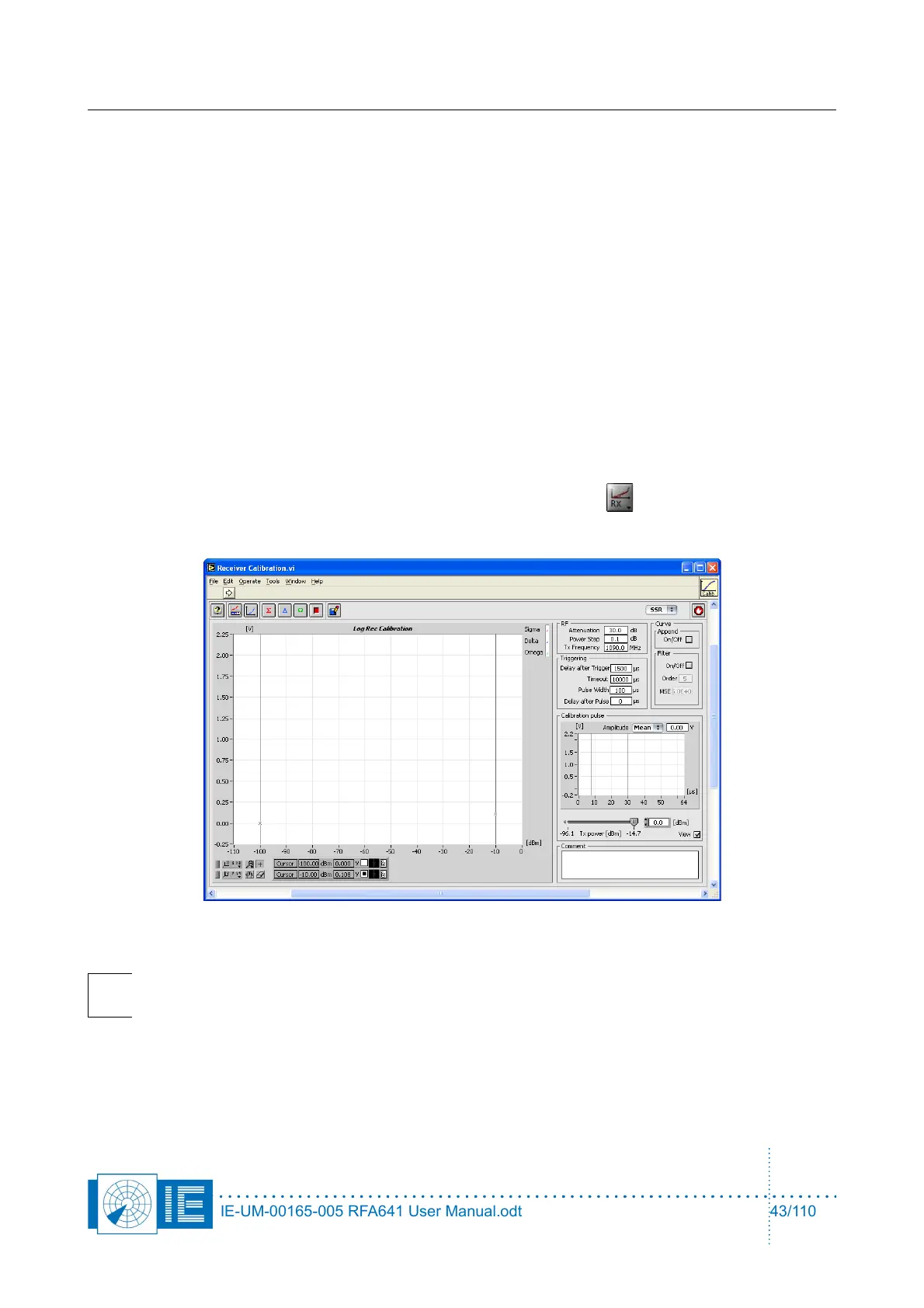
4.1.2. Getting Started
The Radar Rx Calibration is loaded from the RASS-S Toolbox using the Rx button.
Make the connections as shown in Annex 3: Rx, Bandwidth and STC Calibration Connection Diagram.
Warning: Make sure the radar Transmitter is switched off on the channel under test and that
automatic channel switching is off, before connecting the RFA Tx output to the radars
receiver RF Input.
IE-UM-00165-005 RFA641 User Manual.odt 43/110