Radar Field Analyser - RFA641 Edition Date: 28-Feb-18
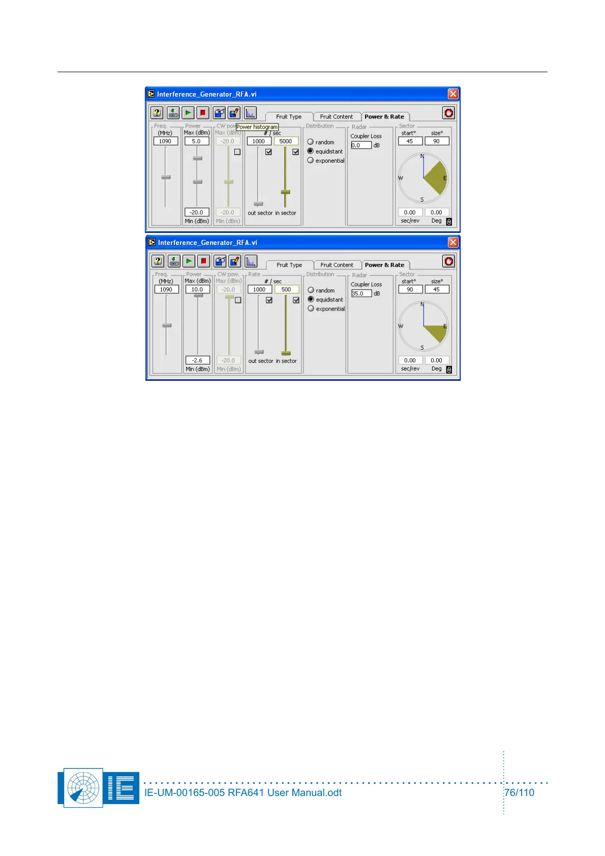
On the Power & Rate panel, the following settings are possible:
• Carrier frequency of the FRUIT and CW.
• The FRUIT power is randomly generated, defined by a uniform range distribution between the Min
and Max boundaries in accordance with a 20 dB/dec propagation law. The minimum and maximum
power values are the powers at the radar input. To determine these correctly, the software needs the
user to input the coupler loss between the output of theRFA and the input of the Radar.
• The CW interference power is randomly distributed between the Min and Max boundaries. When the
minimum differs from the maximum, the amplitude of the CW interference signal changes at a 2 KHz
rate. CW interference can only be generated “in sector”. The CW interference can be switched off
with the check box.
• There are two different sectors for the generation of interference: in sector and out sector. The in
sector and out sector FRUIT rates can individually be switched off with their respective check
boxes. Notice that the combination of FRUIT and CW is only possible in sector. The time gaps
between the FRUITs are then filled with CW interference.
• It is possible to chose between a random, an equidistant or an exponential FRUIT distribution in
time. The Interference Tool can not generate overlapping FRUIT. Therefore inter arrival times
(exponential distribution) smaller than the previous FRUIT length are not possible.
• The in sector is defined by a start angle and a size angle and is represented in a different colour on
the azimuth indicator in the Sector section. The out sector is then automatically the full circle minus
the in sector. The blue line in the azimuth indicator indicates the current azimuth which is also
digitally indicated below the analog azimuth indicator. There are two different methods of ACP/ARP
generation for the RFA FRUIT generation. Either the revolution speed of the Interference Tool is set
with the sec/rev control. In this case ACP and ARP are generated internally and the Interference
Generator runs asynchronous to the radar. The other possibility is to slave the Interference Tool on
the ARP/ACP of the radar under test with the lock to ARP button in the lower right corner of the PPI
indicator. In this case the ARP/ACP of the radar under test is used to synchronize the interference
scenario. The ARP/ACP of the radar can be fed to the RFA641 through the digital input on the back
panel.
IE-UM-00165-005 RFA641 User Manual.odt 76/110