Radar Field Analyser - RFA641 Edition Date: 28-Feb-18
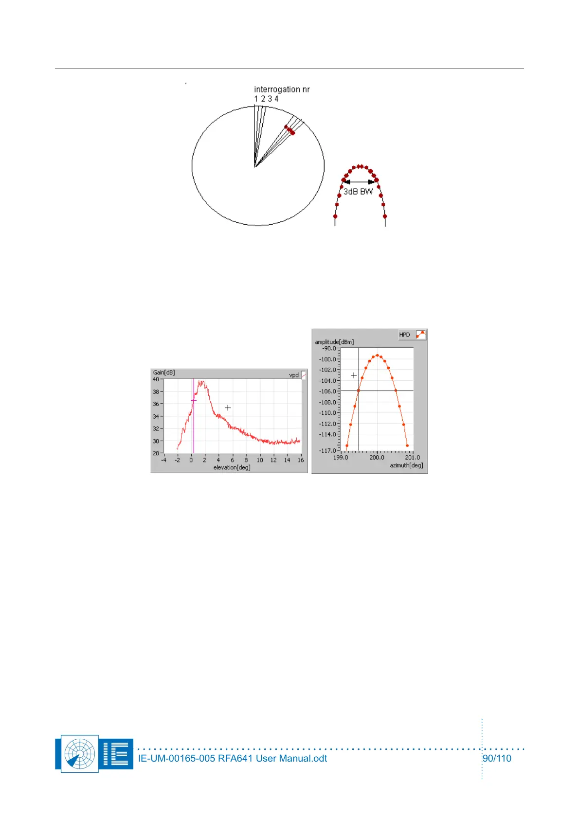
The simulator also accurately simulates the horizontal and vertical antenna diagram. The vertical diagram
(typically antenna gain versus elevation) can be entered as a VPD diagram (measured as a solar or as
import from spreadsheet data) .
The horizontal diagram is calculated as a mathematical parabolic curve with a predefined 3dB beamwidth.
Typically, the target is generated over 20 dB dynamic range. Out of beam echos lower than 20 dB are not
generated.
10.1.3. Software Principles
The Target injection tool consists of two software modules, which can both be loaded from the RASS-S
toolbox. The first tool is used to create the scenario. This can be performed by opening the Trajectory
scenario generator tool and following the correct instructions for generation of a target generation scenario.
All the details of the scenario generator can be found in the RES scenario generation manual.
One should especially take care not to generate overlapping targets, since this it is not possible to generate
such targets using this generator.
The PSR target generator typically uses the output (S4TJ) file of the trajectory scenario generator, so the
same principles as used for generation of RES targets can be applied. Of course PSR targets do not have an
A code or S address, but we advise you to generate a unique A code for every target anyway. This A code
can be used for selection of a certain target, e.g. when recording video automatically.
The second tool consist of the actual target injection part and the compiler, which requires a number of steps
to be performed:
• Selection of the scenario to be replayed
• Selection of the Vertical diagram of your antenna (Solar curve or import of curve)
IE-UM-00165-005 RFA641 User Manual.odt 90/110