Radar Field Analyser - RFA641 Edition Date: 28-Feb-18
5. DOWNLINK MEASUREMENT
5.1. Theory
The Downlink measurement enables the user to measure the HPD antenna pattern at reception. The
RFA641 is set-up in the field as the RF downlink source transmitting SAM (Synchronous Amplitude
Modulated) pulses. In most cases, these pulses are in fact synchronized with the radar’s interrogations, to
avoid interference with real radar replies and avoid operational impact. The test pulses are then measured at
log video level at the output of the (M)SSR or PSR receiver using the RIM782 (further explanation can be
found in the RIM782 manual). This chapter will explain the function of the RFA641 in the downlink
measurement.
5.2. Getting Started
When the RIM782 is set-up at the radar site according to the RIM782 manual, it is time to set-up the RFA641
in the field (the same location as for an Uplink measurement can be used, tips to find a good location can be
found in section 3.1. ). The set-up is shown in Annex 7: RFA641 Downlink Connection Diagram. When the
RFA641 is set-up, open the Uplink tool from the RASS-S toolbox using the Uplink button.
5.3. Software
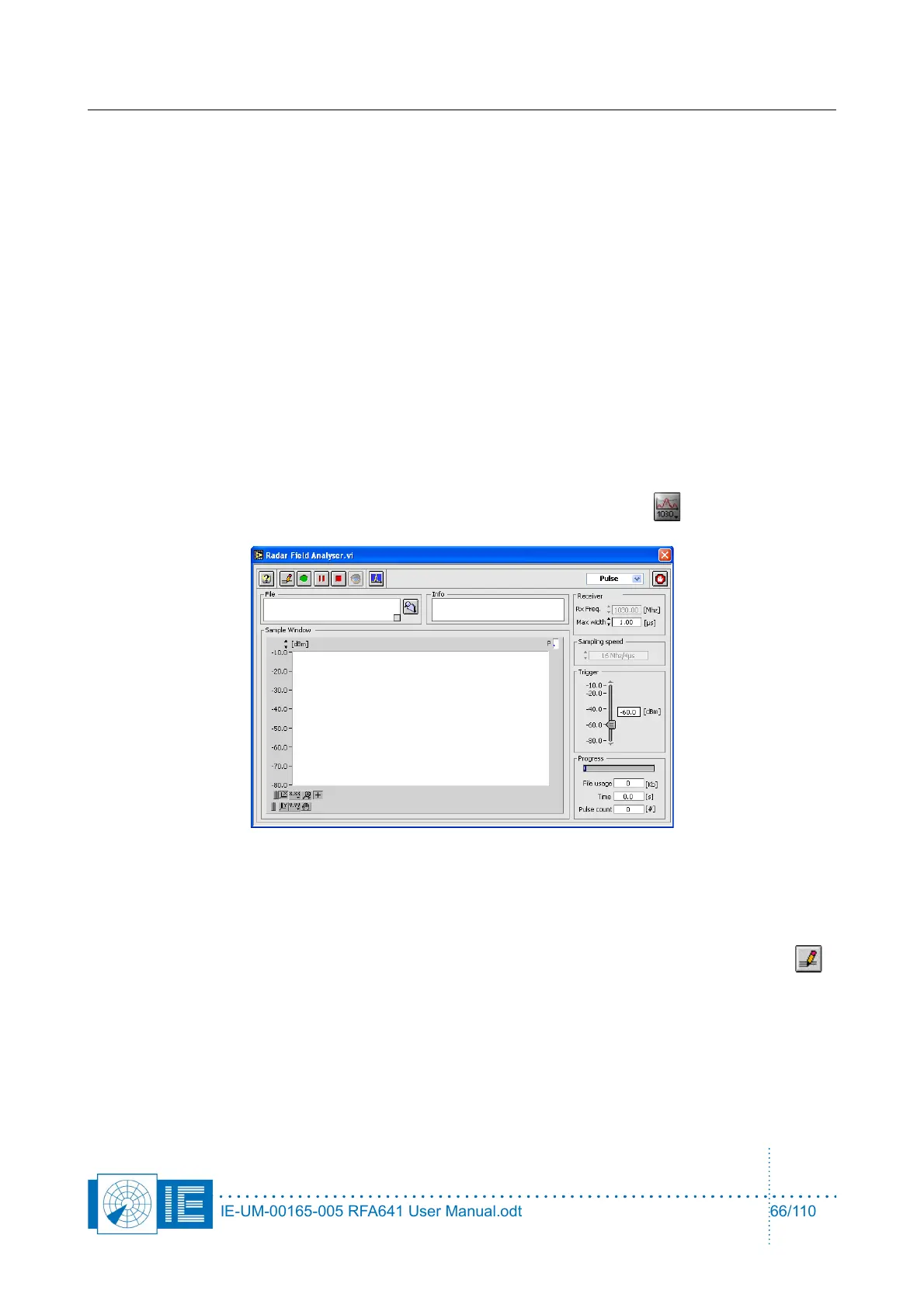
1. The Uplink program contains 4 different programs which can be selected via the selector shown in
figure 9. For the downlink function the Transmit program needs to be selected as it transmits pulses
or CW using the RFA641’s transmitter. As soon as the Transmit program is selected, the
HPD_Preferences window will pop up (this window can also be evoked using the Preferences
button) at the Downlink settings tab.
IE-UM-00165-005 RFA641 User Manual.odt 66/110