Radar Field Analyser - RFA641 Edition Date: 28-Feb-18
selected delay. To have an initial idea of the (D)STC range and power levels you can control the time
delay of the RF test pulse (and the related measurement window) by adjusting the Trigger Delay
control.
3. If you want to perform the RFA Selftest/Calibration, this is possible by clicking the Cal RFA
button.
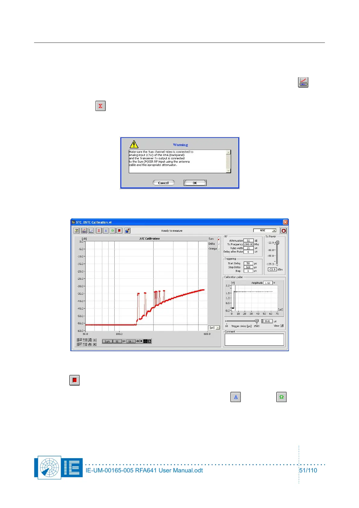
4. Click the Sum button to measure the ∑ channel.
A dialog box will prompt the user to check the connections of the different channels to the back panel
Ch2 and the Tx of the RFA641. Confirm the connections by clicking the OK button.
While the measurement is performed, the result is immediately visible.
In case the measurement result is not as expected, the procedure can be halted by pressing the
Halt button.
5. For MSSR stations: proceed with the measurements of the Delta and Omega channels.
Press the respective buttons on the software front panel, change the connections as described in the
pop-up window and repeat step 4.
IE-UM-00165-005 RFA641 User Manual.odt 51/110