Radar Field Analyser - RFA641 Edition Date: 28-Feb-18
sweep parameters above explained is changed, the graph is cleared and the frequency sweep starts
over from the selected start frequency on.
4. Click the Return button to close the panoramic sweep window, and to return to the RFA
Recorder.
3.3.2. RFA Recorder: Using the External Video Input
The RFA recorder allows the use of the external video input of the Radar Field Analyser as input for the HPD
recording. This option is implemented for users who want to perform HPD measurements for radar systems
that operate at frequencies outside the RFA frequency range. For this purpose you will need an external RF
receiver or in case you have a spectrum analyser available with an analogue video output, you can use this
as RF front-end for the HPD measurement, provided its video output level matches the 0...+2V input voltage
range of the RFA external video input and the bandwidth (both RF/IF and video) is sufficient.
A receiver calibration curve will be required to define the relationship between the input power level at the
receiver or spectrum analyser input (dBm) and its output voltage (V). For a known RF receiver, it is possible
to define it by just using a slope and offset parameter. For a high quality spectrum analyser the receiver
curve will be independent of the frequency used. This allows performing a receiver calibration at a frequency
within the RFA frequency range (so using the RFA) and using the resulting calibration table at any other
frequency that can be selected on that spectrum analyser.
Depending on the quality of the spectrum analyser, the absolute power level might be changing with the
selected frequency. This introduces an offset in power, which is less important for HPD measurements (since
we are only interested in the relative power levels), but it is something you must be aware of.
The selected RF/IF and video bandwidth will influence the measurement when wrongly set. They must be set
to a sufficient bandwidth to prevent the pulses being smoothed.
Use the scope mode of the RFA recorder program to examine the pulse shape of the pulses received. Verify
whether pulses reach their maximum power level within the expected pulse width.
1. Setup the Radar Field Analyser. The only signal connection to be made to the RFA641 is the
connection of the spectrum analyser video output to the RFA external video input, available at the
back of the RFA, at the analogue input marked CH2. Please verify that the video level signals are
within the 0...2V input voltage range. Your spectrum analyser input is assumed to be connected to an
appropriate measurement antenna (suitable for the frequency range of interest).
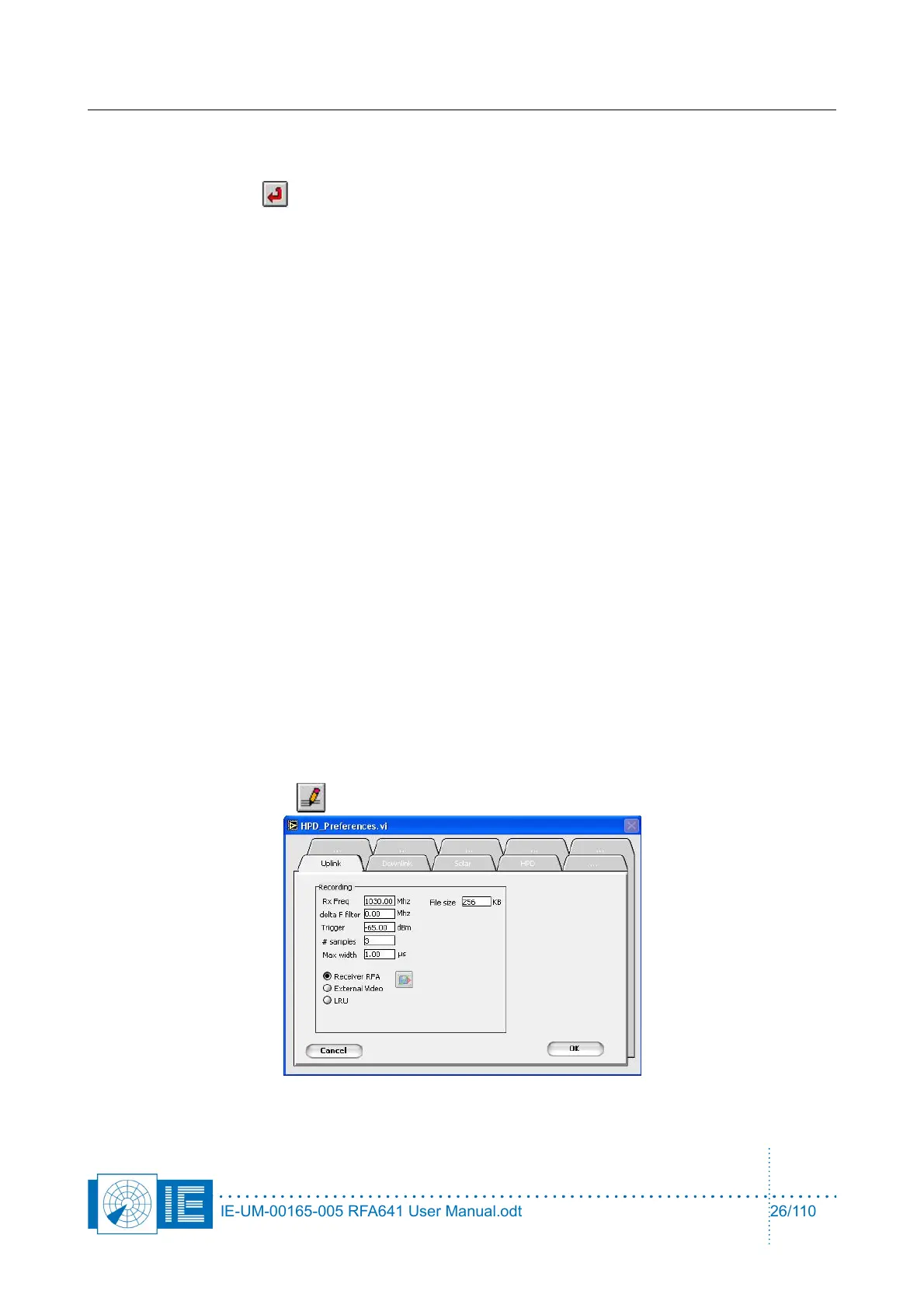
2. Click the Parameters button. The HPD Preferences window will pop up:
IE-UM-00165-005 RFA641 User Manual.odt 26/110