Radar Field Analyser - RFA641 Edition Date: 28-Feb-18
The external attenuator added is typically 30dB in order to reach the maximum receiver input power
of about -20 dBm. In most cases however, the connection will take place through a fixed coupler
already present in the system. This attenuation must also be taken into account when filling in the
Attenuation parameter.
During the DSTC measurement power will be swept from maximum power to minimum power using
the Power Step value to determine the power levels used. Each other scan the power will be
decreased by the value in Power Step.
2. Set the time sweep parameters: The sweep Start Delay is used to determine the time delay
between the first test pulse and the trigger pulse. The Stop Delay is used to determine the time
delay between the last test pulse and the trigger pulse. The RFA641 transmits a set of 128 Rf
pulses, spread over the selected range from the set minimum (Start Delay) to the set maximum
(Stop Delay) to measure the complete (D)STC at once at the azimuth of the interrogation.
3. The #sectors parameters determines the number of measurements to be executed during one
revolution. In fact it acts as a divider for the IPR count, so that each IPR/#sectors amount of triggers
a measurement is performed.
The interrogation trigger signal is used both as start of range and as azimuth indicator. Due to
limitations of the RFA641 digital input hardware, only two timing signals can be connected
simultaneously. Therefore the interrogation count is also used to calculate azimuth.
The program will synchronize to the ARP and interrogations of the radar. The azimuth information is
indicated in the PPI Pict window. Once the number of interrogations per revolution (IPR) is constant,
the azimuth can be calculated correctly and the measurement buttons are enabled.
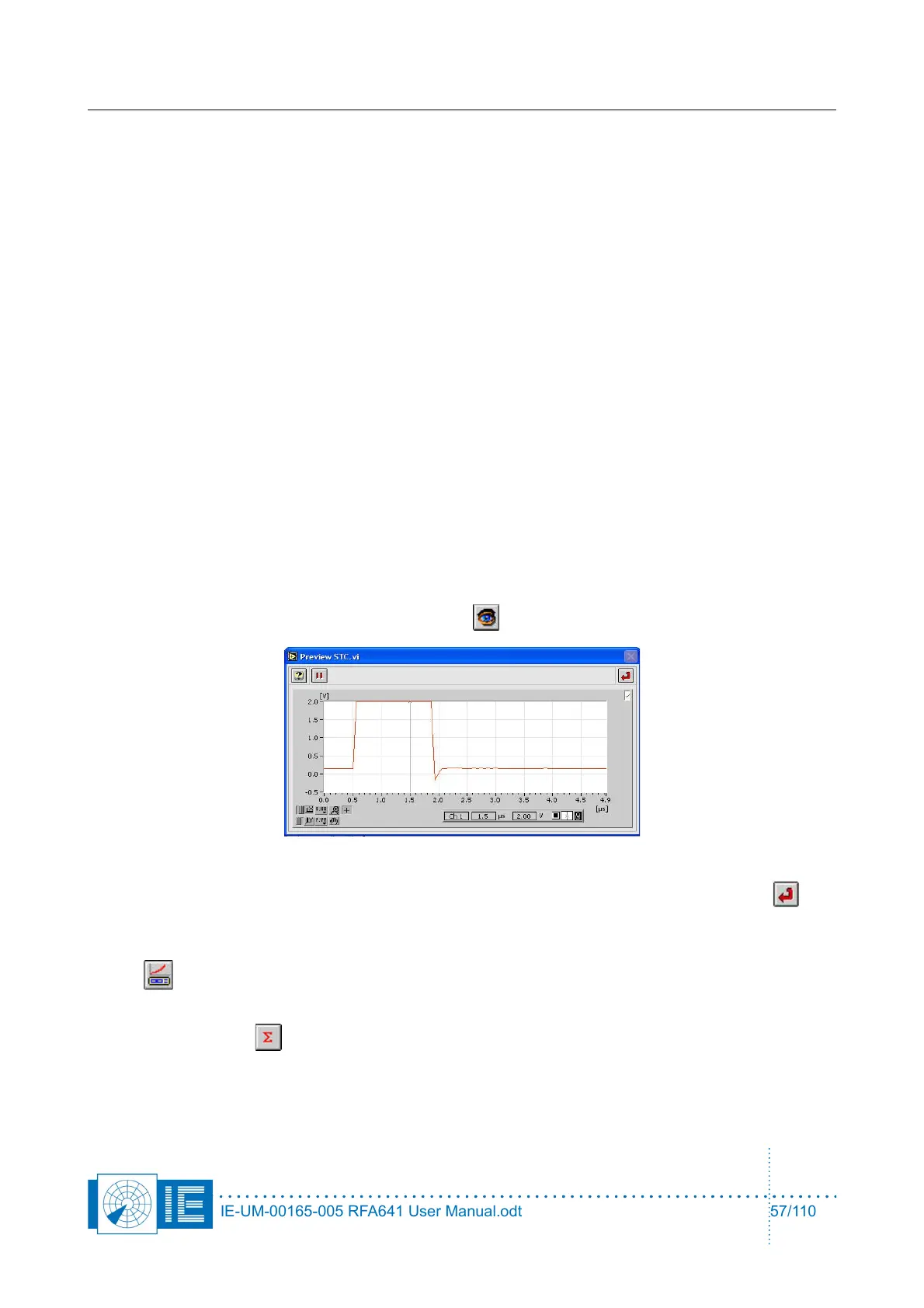
4. Before starting the measurement it is important to check the position of the output pulse and the
setting of the sampling point. Click the Preview button to open the Preview STC.vi window.
Use the cursor to set the sampling point for the pulse amplitude. Once set, click the Return
button to return to the sectorial DSTC measurement program.
5. If you want to perform the RFA Selftest/Calibration later on, this is possible by clicking the Cal RFA
button.
6. Make the correct connections for measuring the ∑ channel as described in the set-up window and
click the Sigma button. A dialog box will prompt the user to check the connections of the
different channels to the back panel Ch2 and the Tx of the RFA641. Confirm the connections by
clicking the OK button.
IE-UM-00165-005 RFA641 User Manual.odt 57/110