Radar Field Analyser - RFA641 Edition Date: 28-Feb-18
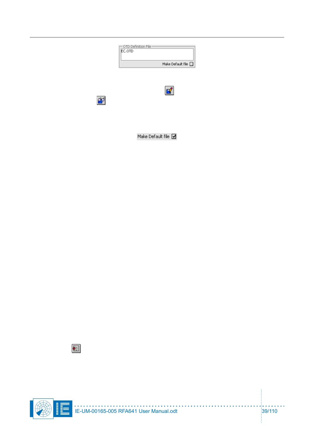
The user can change any of these parameters and save the set of limits to a new file in order to create a new
OTD definition file. This can be done by clicking the Save button. In case you want to change the OTD
definition file, click the Load button.
In some cases you might want to set your OTD definition as default calculation. Check the Make Default file
checkbox upon closing the OTD program, the active OTD definition file will be set as the default file to be
loaded whenever the OTD program is called.
The following list describes the OTD limits that can be set by the user. Please note that all limits are defined
as relative to the SUM/PSR max power level.
1. SUM/PSR 3dB Beamwidth Min, Max [deg]: Allowed min. and max. for the 3dB beam width
2. SUM/PSR 10dB Beamwidth Min, Max[deg]: Allowed min. and max. for the 10dB beam width
3. Sum/PSR Max sidelobe level [dB(m)]: Allowed max. for the Sum/PSR max. Sidelobe level.
4. Sum/PSR Max Backlobe level [dB(m)]: Allowed max. for the Sum/PSR Backlobe level.
5. Omega Notch Depth [dB(m)]: Allowed max. for the Omega Notch Depth.
6. Sum, Omega Crossovers: Power [dB] min, max: Allowed range for the crossover level.
7. Delta Az [deg] Max: Allowed max. azimuth difference for the crossovers to be recognized as
symmetrical.
8. Delta Notch Depth [dB(m)]: Allowed max. for the Delta Notch Depth.
9. Sum, Delta Crossovers
10. Power [dB] Min, Max: Allowed range for the crossover level
11. Azimuth [deg]: Allowed max. azimuth for the crossover position.
12. Delta Az. [deg] Max: Allowed max. azimuth difference for the crossovers to be recognized as
symmetrical.
For each of the limits defined the corresponding parameter is checked. In case the calculated antenna
parameter is outside the set limits an error message is created in the OTD Error Messages window. This
contains the statements that the parameters are outside specification and displays the parameters result and
the set limits. In case of punch-throughs, a list of the punch-throughs is created indicating level and azimuth
of each punch-through.
Using the Export button you can export the OTD parameters, limits and error messages to a tab-
separated file.
IE-UM-00165-005 RFA641 User Manual.odt 39/110