Radar Field Analyser - RFA641 Edition Date: 28-Feb-18
16. A number of important parameters are shown. The parameters are checked against the Eurocontrol
standards for Radar Performance. If wanted the user can set his own limits for the calculated
parameters (as explained in section 3.3.5. ). Malfunctions are shown in red.
Caution: Beware the OTD calculations assume equidistant points, so if the stagger period is
more than 5% off the average period, use the Spline function before calculating the OTD
parameters.
17. Click the Return button to leave this window.
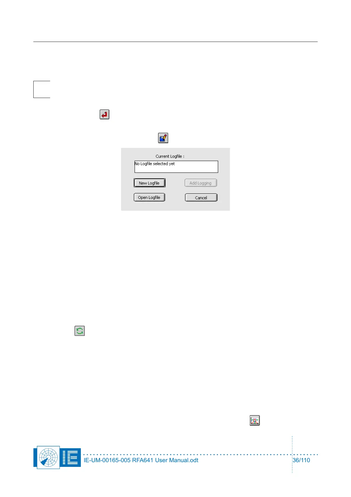
18. The curve can now also be logged to disk and reviewed later using the View HPD Logfiles function
from the Radar Toolbox. Use the Save button to evoke the Log panel.
If no logfile has been selected yet: Open an existing logfile with the Open logfile button or create a
new logfile with the New Logfile button. In both cases a file dialog will appear. After selecting a
logfile (a new or an existing one), use the Add logging button to add the current data.
If a logfile has already been selected: the logfile string indicates the selected file name. Use the Add
Logging button to append the current data to the logfile.
19. The program will automatically return to View RFA Pulses window.
20. Repeat creating HPD loggings from the different revolutions present, adding them to the same
logfile. Use the index to select different revolutions. We have now completed the cycle starting with
recording pulses using the Radar Field Analyser up to creating HPD antenna diagrams in an Uplink
logfile. If, for any reason, you are not pleased with the extracted HPD diagram (for example if the
parameters were not set correctly, or the boresight was not set correctly), you can revert to the
original pulse data and reselect the stagger pattern or change any parameter by simply clicking the
Revert button. The graph will revert to the original pulses.
3.3.4. Averaging Multiple HPD Diagrams
In case the interrogations are asynchronous to the revolution, it is possible to interleave multiple HPDs. This
way the sample rate can be virtually increased in order to come to a better definition of the actual HPD.
The only requirement is that the recorded RFA pulse file is of sufficient length (# of revolutions recorded).
The View RFA Pulses program is capable of performing this interleave function. The following check list will
allow you to perform such action.
1. Perform an antenna diagram extraction as explained above.
2. Once the selected HPD is ready to be inserted into the reference, click the HPD button again.
IE-UM-00165-005 RFA641 User Manual.odt 36/110