Radar Field Analyser - RFA641 Edition Date: 28-Feb-18
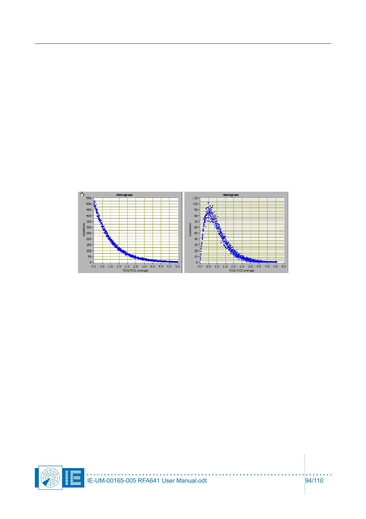
the return power will be variable according to a Raleigh distribution.
• Type: The type of Radar Cross section that is simulated: This selector selects the type of swirling
case to be generated. The swirling case changes the RCS according to a statistical function. The
distribution is described in many reference works, but we used the distribution from M.l. Skolnik,
"Introduction to Radar Systems".
◦ Fixed RCS means the return power is fixed in time and space.
◦ Swirling type I means the reply power of the target changes from scan to scan according to the
Rayleigh distribution.
◦ Swirling type II means the reply power of the target changes from reply pulse to reply pulse
according to the Rayleigh distribution.
◦ Swirling type III means the reply power of the target changes from scan to scan according to a
modified distribution.
◦ Swirling type IV means the reply power of the target changes from reply pulse to reply pulse
according to a modified distribution.
• RFA Attenuator: The attenuation between the RFA641 output (Tx connection) and the input of the
radar receiver. This attenuation is added to the calculated return power to determine the RFA641
output power.
• Pulsewidth: The pulsewidth of the generated returns.
• Target Zero Range: The range in µs of the trigger signal. This value is subtracted from the scenario
range before the target is being generated. So if you have a pre-trigger, the zero range value should
be negative.
• Extra Attenuation Fixed: An extra attenuation (e.g. radome loss) to be added to the radar equation
in order to calculate the target return power.
• Extra Attenuation Variable: A variable attenuation value (e.g. atmospheric influence) to be added
to the radar equation.
• Use Atmospheric attenuation: Calculated atmospheric loss according to "Radar Range
Performance Analysis" by Lamont V.Blake. This calculation uses elevation, frequency and range to
determine the atmospheric attenuation of the radar signal. The calculation is performed based on the
graphical interpretation of the curves presented in the reference and therefore it has a limited
accuracy of 0.1 dB.
• Use Lens-effect: This check box takes the lens effect into account into the radar equation. The lens
effect especially is important in low elevations. Calculated lens effect loss; according to "Radar
IE-UM-00165-005 RFA641 User Manual.odt 94/110