Radar Field Analyser - RFA641 Edition Date: 28-Feb-18
3.3. Software
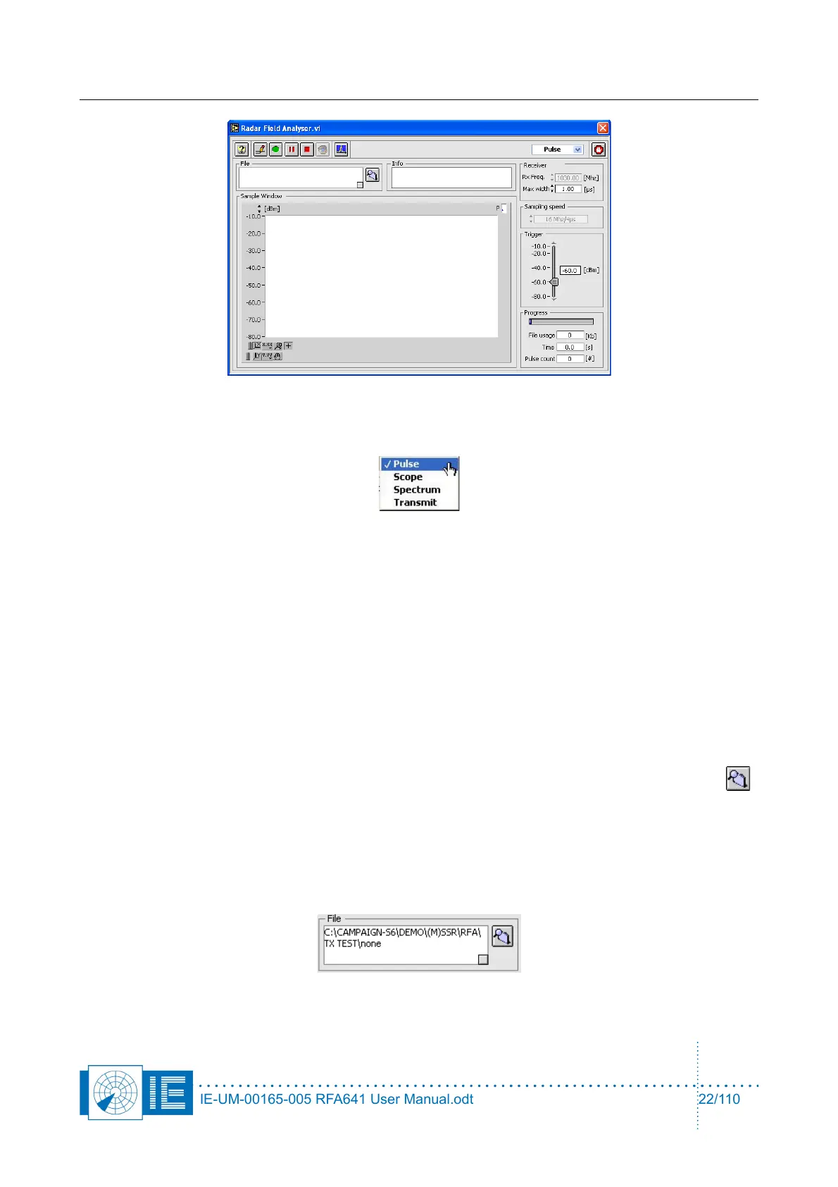
1. The RFA Recorder software contains four programs:
• Pulse program: records pulses in a compact format (8 bytes/sample). The data recorded is
minimized describing only the amplitude and timing of each pulse in 8 bytes. One should use
this program for all Uplink HPD measurements.
• Scope program: records detailed pulse images in 62 samples (128 bytes/pulse). The Scope
program logs the complete pulse shape to disk since 128 bytes are used for each pulse. This
program can be used to record pulses in special conditions, such as in extreme reflective
environments or to completely view the pulses if no oscilloscope is available.
• Spectrum program: scope recording with FFT converts the pulse images into pulse spectrum.
• Transmit program: controls the transmission for the Downlink measurement. The Transmit
program is used to transmit pulses or CW using the RFA’s transmitter for Downlink purposes.
2. Before starting a recording, first select or create the destination folder by using the Find Folder
button. When clicking this button, a folder dialog will appear asking you to select a folder to store the
recordings. By default, the folder dialog will open with the RFA subdirectory of the MSSR or PSR
subdirectory of the active campaign folder as the starting point.
In case you want to create a new folder: click the New button, enter a file name and click Create.
Click Select and the desired folder is selected or created. The File indicator of the Radar Field
Analyser program will show the complete destination path for the pulse recordings, followed by
“\none”.
IE-UM-00165-005 RFA641 User Manual.odt 22/110