Radar Field Analyser - RFA641 Edition Date: 28-Feb-18
RFA641 frequency ranges from 800 to 3500Mhz. The frequency sweep is usually set to 30MHz,
while the step is set at 0.1MHz.
3. Set the Trigger selection. The Bandwidth measurement is performed at a certain delay after the
trigger pulse: be sure to set the Delay after Trigger value. If the measurement is performed without
applying a trigger pulse, the tool will use a PRF of 1/Timeout.
The Calibration Pulse field continuously monitors the signal available on the Ch2 video input at the
selected frequency. You can control the frequency directly by adjusting the Tx frequency control and
check the pulse shape and amplitude available.
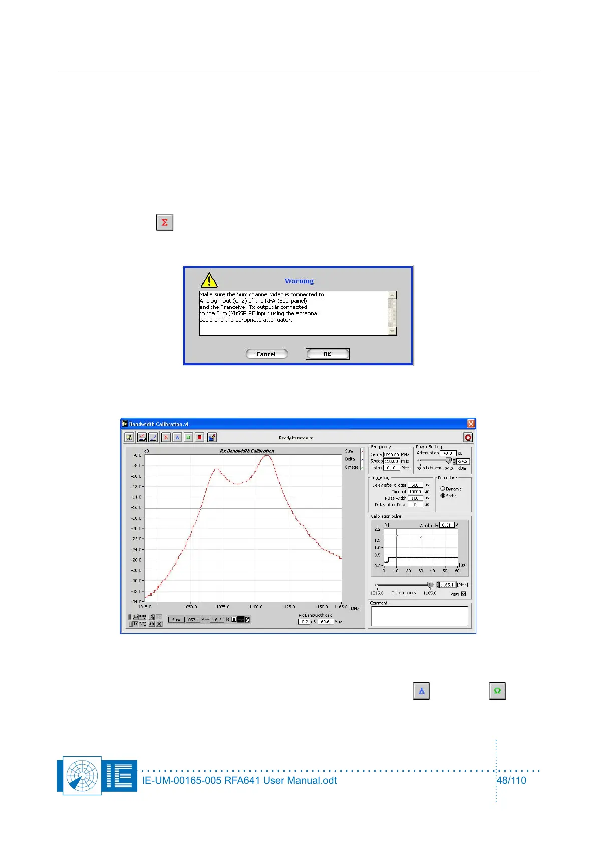
4. Make the correct connections for the calibration of the ∑ channel according to the set-up window and
click the Sum button.
A dialog box will prompt the user to check the connections of the different channels to the back panel
Ch2(In) and the Tx of the RFA641. Confirm the connections by clicking OK.
Next, the frequency sweep is carried out. The bandwidth curve is measured and the 3dB and 10dB
bandwidths can be calculated.
Enter 3 dB or 10dB in the Rx Bandwidth calc field and the respective filter bandwidths will be
calculated and displayed.
5. For MSSR stations: make the correct connections to measure the Delta and Omega
channels and repeat step 4.
IE-UM-00165-005 RFA641 User Manual.odt 48/110