Radar Field Analyser - RFA641 Edition Date: 28-Feb-18
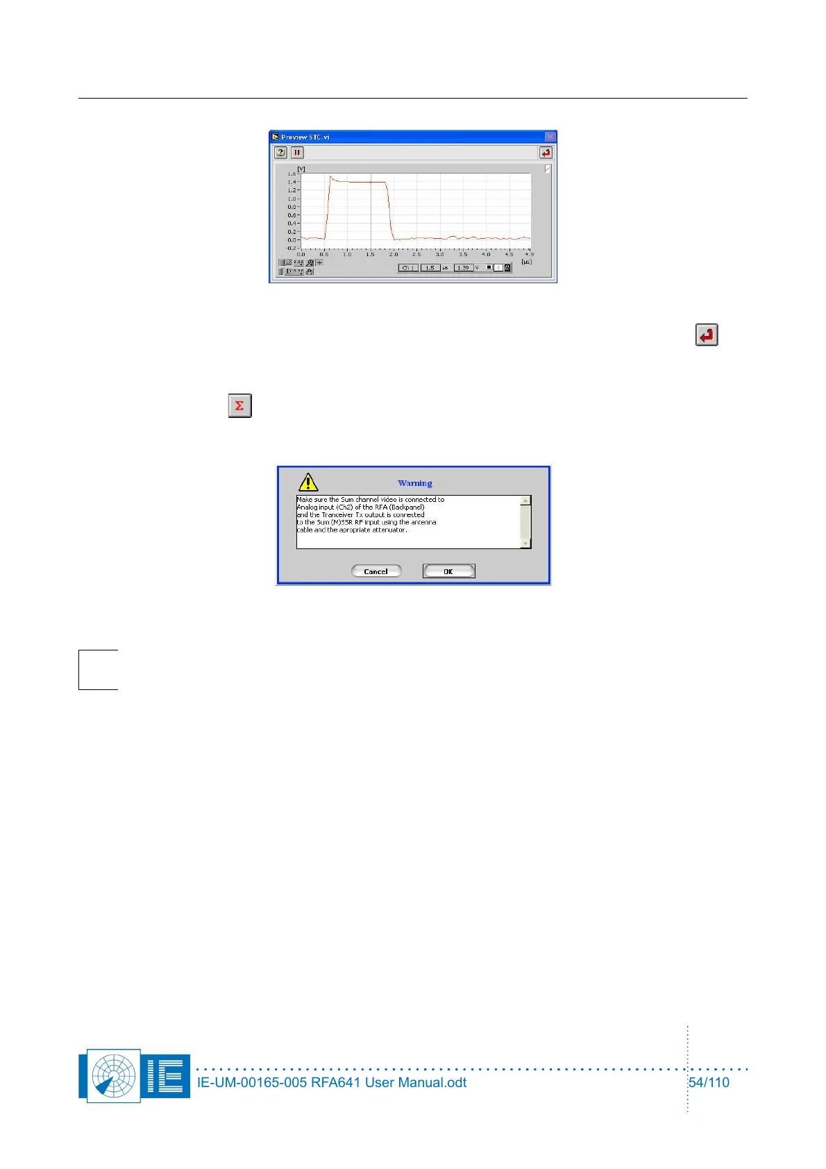
Use the cursor to set the sampling point for the pulse amplitude. Once set, click the Return
button to return to the sectorial STC measurement program.
7. Make the correct connections for measuring the ∑ channel as described in the set-up window and
click the Sigma button. A dialog box will prompt the user to check the connections of the
different channels to the back panel Ch2 and the Tx of the RFA641. Confirm the connections by
clicking the OK button.
Note: The channel selection button is only used to select the correct Rx Calibration table
(correct channel). The measurement is a single channel measurement.
8. Upon the ARP following the start of the measurement, the PPI Graph containing the sectorial STC
map is updated with the measurement result for the full revolution at once.
IE-UM-00165-005 RFA641 User Manual.odt 54/110