Radar Field Analyser - RFA641 Edition Date: 28-Feb-18
4.3.3. Software
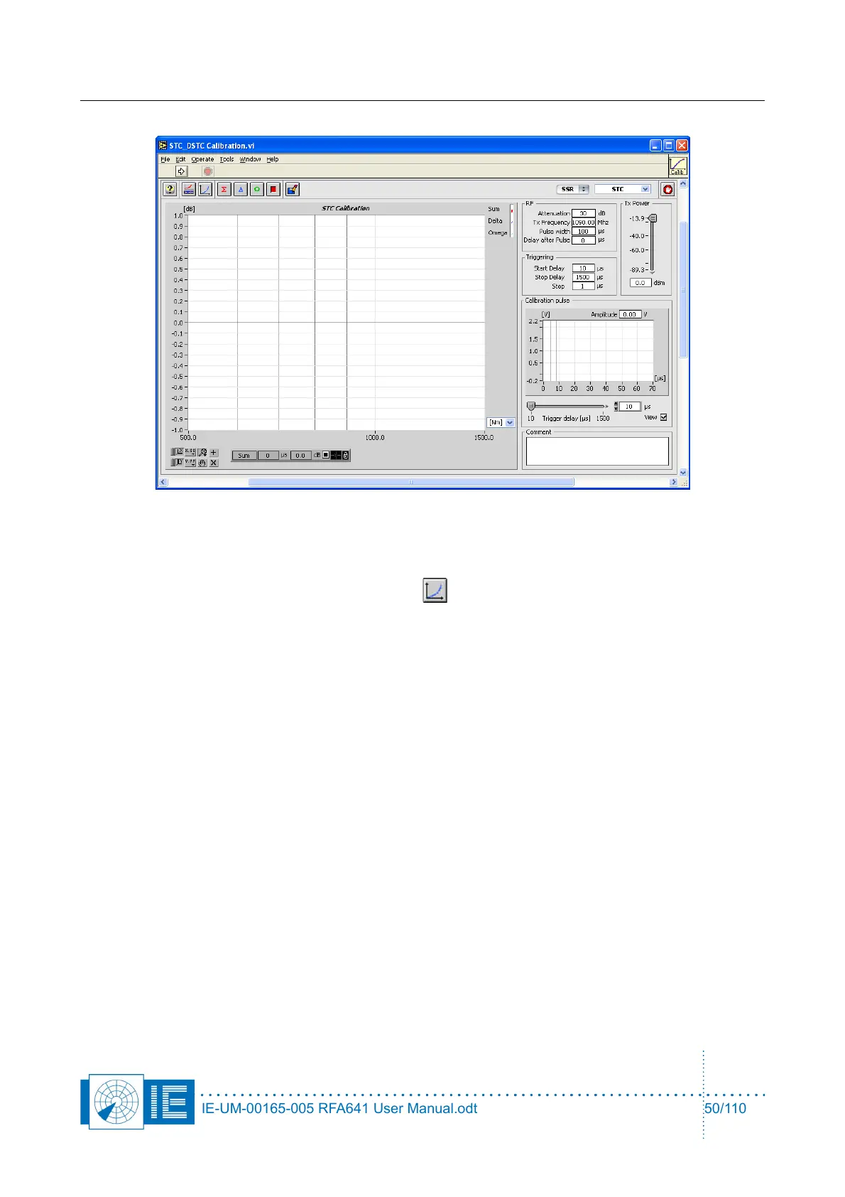
The software will ask to load the correct receiver calibration file after you have started the tool. This is
necessary to be able to calculate the exact power level corresponding to the measured pulse amplitudes.
This can also be done using the Load Rx Calibration button. The selected calibration file is then
displayed. By clicking Cancel in the file dialog it is possible to select a default table, in case no receiver
calibration file is available. Use Slope and Offset to change the default table to your needs.
1. Adjust the Rf parameters and the Tx Power control as needed. Select the correct Tx frequency
(default 1090MHz). The Tx power control sets the power level present after the extra attenuation at
the RFA641’s Tx connector, so indicating the power injected in the radars Rx input. The max. output
power of the RFA641 is guaranteed +10dBm at 1090Mhz. Choose a level in the linear calibration
part of the radar Rx to obtain a satisfactory result. Typically it is set so that the Rx receives a power
level of -40 to -50dBm.
The external attenuator added is typically 30dB in order to reach the maximum receiver input power
of about -20dBm. In most cases however, the connection will take place through a fixed coupler
already present in the system. This attenuation must also be taken into account when filling in the
Attenuation parameter. Therefore if the receiver is measured through an extra fixed coupler of
30dB, the transmission power must be set to -50dBm, extra attenuation in this case is 60dB.
The width of the test pulse can be set using the Pulse width parameter.
Delay after Pulse determines the start of the sample window to capture the test pulse at the video
level output of the Rx. This is foreseen in case a processing delay exists in the system.
2. Set the Triggering parameters:
The sweep Start Delay is used to determine the minimal time between the test pulse and the trigger
pulse. The Stop Delay is used to determine the maximum time between the test pulse and the
trigger pulse. The Step parameter determines the step size of the time sweep.
The Calibration Pulse field continuously monitors the signal available on the Ch2 video input at the
IE-UM-00165-005 RFA641 User Manual.odt 50/110