Radar Field Analyser - RFA641 Edition Date: 28-Feb-18
3. The less frequently altered Uplink parameters (and in a later stage you will need also the Analysis
parameters) can be changed in the preferences window that can be recalled by pressing the
Parameters button. The most commonly adjusted parameters are also put on the RFA
Recorder’s front panel.
Only the parameters for Uplink Recording are of importance at this stage. These parameter settings
are saved with the recorded data. The range, increment and defaults of the following parameters are
shown between square brackets: e.g. [900..3500 , 1 / 1030].
• Rx Frequency (MHz): [900..3000/3500, 1 / 1030]: This parameter controls the frequency
selection setting of the RFA receiver and of the YIG filter. It can be set between 900 and 3500
MHz in case the internal RF circuitry is used. In case the external video input is selected as
input source these limits do not exist since the RFA driver will ignore this parameter.
• Max Pulse width (µs): [1..64, 1 / 1]: This parameter controls the range of the sliding window
used to determine the pulse amplitude. The parameter must be set slightly larger than the real
pulse width of the recorded pulses. Use the Scope program to verify the pulse width.
• Trigger level (dBm): [ -5..-85, 0.1 / -60]: This level determines the trigger level above which
pulses are recorded.
4. First switch to the Scope program using the Program selector as shown in figure 9,in order to
measure the complete pulse shape instead of only the pulse amplitude.
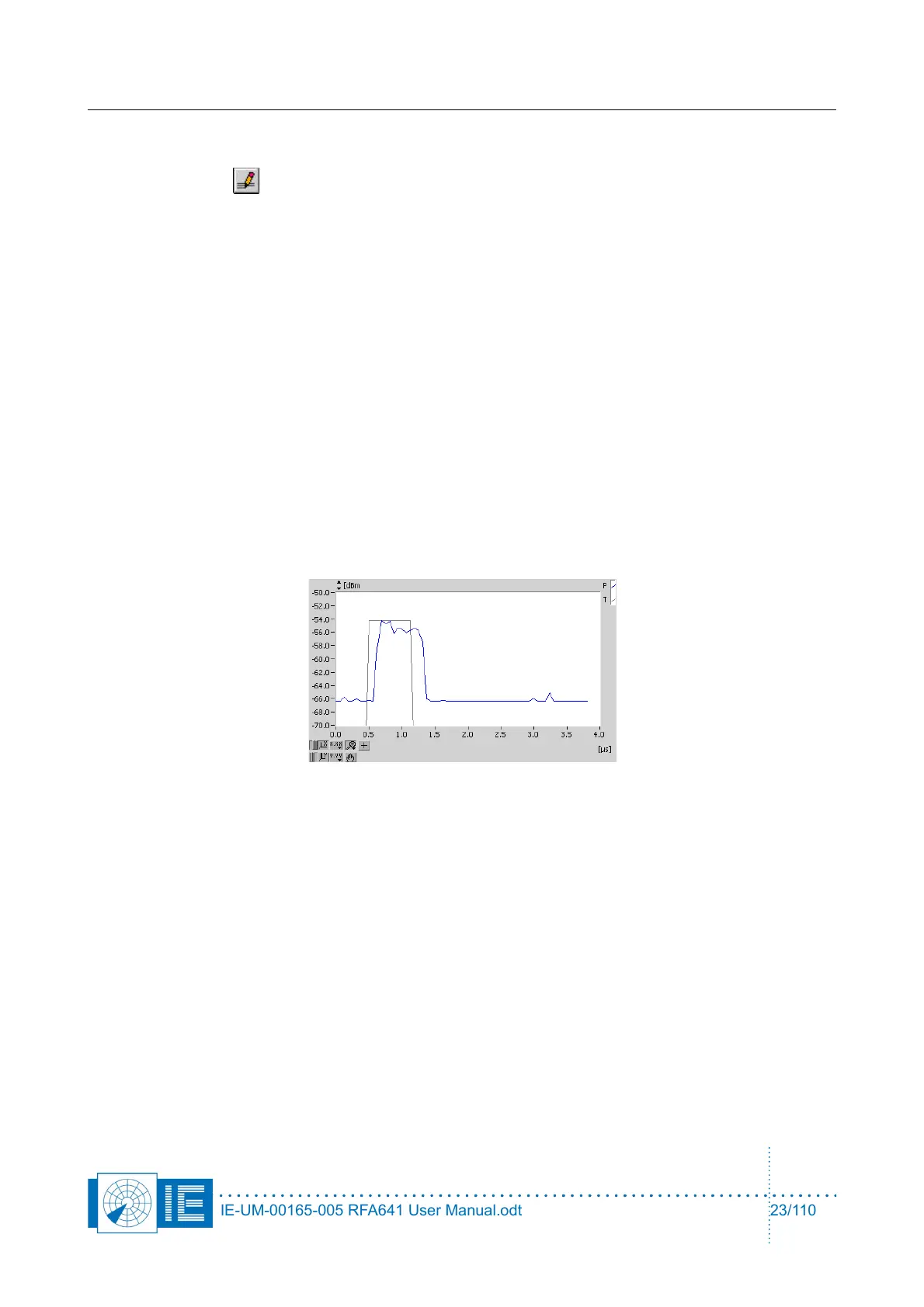
The curve will change appearance:
The blue curve is the receiver video signal as it is sampled by the RFA641. The second (grey) curve
shows the digital output of the threshold detector. This detector output indicates the pulses and pulse
width detected. Using the trigger level slider, the trigger level for pulse detection can be set.
Position the trigger level such that all pulses are detected properly, but no false triggers occur due to
the noise. If the trigger level is too low; only noise will be sampled.
The default sampling frequency of the scope window is 16 MHz, but if you want to monitor (or
record) pulses with longer pulse duration (up to 1ms), you must lower the sampling frequency to 8
MHz or lower. The graph will then show a larger time window of the recorded pulse.
Now switch back to the pulse program.
5. The last 1024 recorded pulses are now continuously shown (Rx video level output) on the main
screen:
IE-UM-00165-005 RFA641 User Manual.odt 23/110