Radar Field Analyser - RFA641 Edition Date: 28-Feb-18
to calculate the 3dB bandwidth and 3dB centre frequency. The results are shown in the YIG Filter
section. An error is indicated in case the YIG filter loss (insertion loss) is higher than 8 dB.
5. The Output Power slider control is now enabled. The Selftest program sets the modulator voltage
and performs a frequency sweep in order to determine the output power (dB) for a number of
modulator voltages. The max. output power is read from file and is assumed to be constant over the
calibration period.
The measurement is performed in two steps: The first step decreases the output power starting from
max. power until the Rx noise level is hit. Before the second step the program will ask you to remove
the 20dB attenuator at the Tx connector. Again the modulator voltage is swept from (max. power
-20dB) to min. while the corresponding power level is measured. The resulting maximum and
minimum Tx power are indicated in the Output Power field. The slider allows you to set the output
power (i.e. in case you want to check the power level with a spectrum analyser). An error is indicated
in case the max. output power is below the specified minimum and in case the dynamic range is not
sufficient.
Even when the max. power is low, the user can use the RFA641 with its limited power. When the
modulator sweep is done, the selftest sequence is ended.
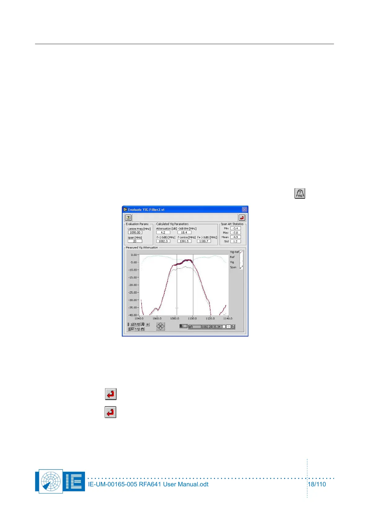
6. It is possible to view the YIG filter attenuation vs. frequency by clicking the View Filter button.
The Evaluate YIG Filter2.vi window will pop up, showing the attenuation vs. frequency of the YIG
filter, measured using the RFA VNA function. From the measurement data the attenuation, 3dB
bandwidth, and 3dB centre frequency are calculated. The Span parameter is used to determine the
frequency span used to calculate the attenuation statistics.
Click the Return button to return to the Selftest program.
7. Click the Return button to stop the Selftest function or to return to the calling function.
When the RFA Self-Test/Calibration procedure is performed without problems, you can continue with the
measurements, knowing the RFA is performing as expected.
IE-UM-00165-005 RFA641 User Manual.odt 18/110