www.javad.com Maxor Operator’s Manual 1-13
INTRODUCTION
Getting to Know Your Maxor
Front Panel
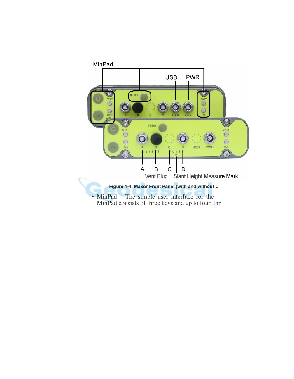
Figure 1-4 shows the Maxor’s front panel components.
Figure 1-4. Maxor Front Panel (with and without USB)
• MinPad – The simple user interface for the Maxor receiver. The
MinPad consists of three keys and up to four, three-color LEDs. See
“Using MinPad” on page 4-2 for descriptions and usages of the
MinPad components.
• Four serial ports:
–Port A used for communication between the Maxor and a
controller or
an
y other e
x
ternal device.
–Port B used internally to connect the receiv
er board with the
Bluetooth® module.
–Port C used internally to connect the modem and receiver boards.
–Port D used for communication between the receiver and an
exter
nal device.
• Vent plug – Equalizes the pressure
between the inside of the
re
ceiver and the outside environment.
• USB – Available on the Maxor GGD with the Euro-112 card and j
n
the Maxor GGDT with the Euro-112
T card, used for high-speed
data transfer and communication between the receiver and an
external device.