JOHNSON CONTROLS
18
FORM 100.50-NOM12
ISSUE DATE: 04/02/2019
SECTION 2 – INSTALLATION
4. Roof structures must be able to support the weight
of the unit and its accessories. Unit must be in-
stalled on a solid level roof curb or appropriate
angle iron frame.
5. Maintain level tolerance to 0.5 inch across width
and 2 inches along the length.
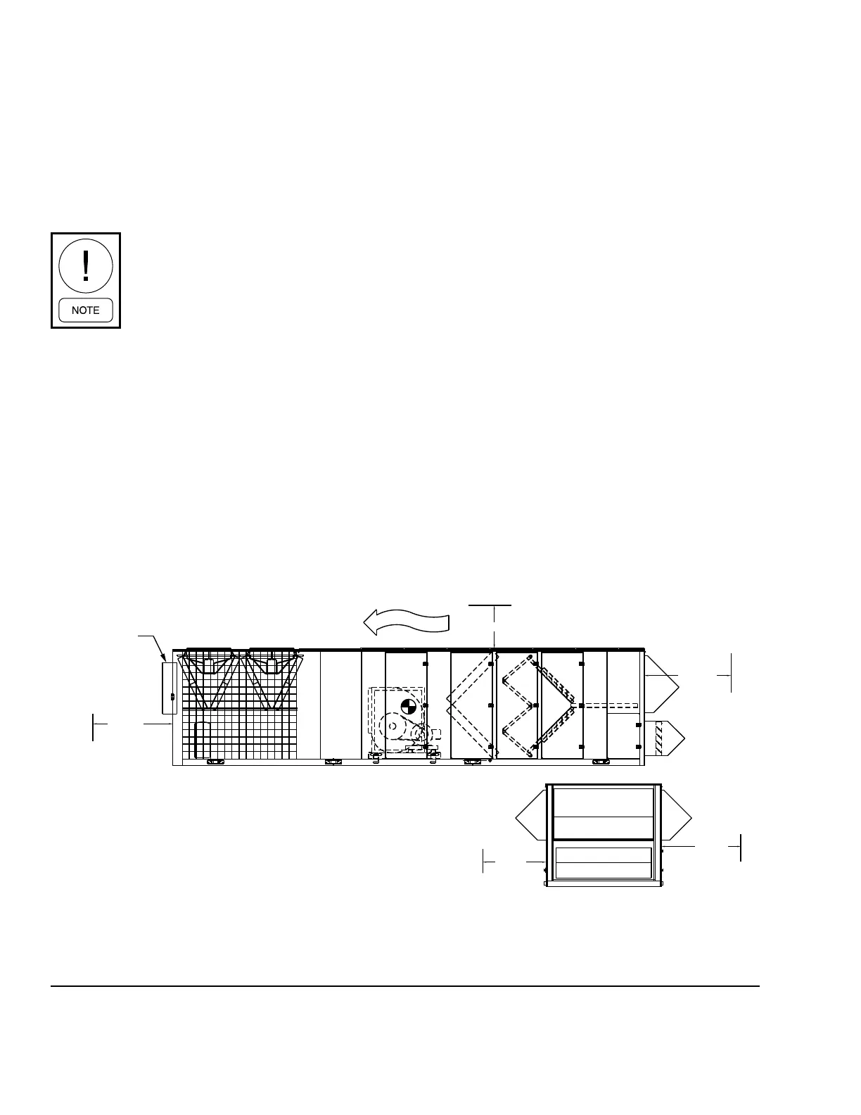
Unit clearances are shown in Figure 3 on page 18.
The clearances shown are to provide
adequate condenser airow and service
access to inside the unit. Additional clear-
ance should be considered for component
replacement such as compressors, evapo-
rator coils, and supply or exhaust fans.
While it is a common practice to operate
the fan as soon as possible (air movement
during construction)on the job site, the
incomplete ductwork and missing diffuser
grilles will greatly reduce air resistance
and will allow the fan to operate beyond
design parameters. This practice may
result in water carry over and ooding of
the unit. Also, the supply fan motor may
overamp and become damaged.
RIGGING AND HANDLING
Proper rigging and handling of the equipment is man-
datory during unloading and setting it into position to
retain warranty status. All lifting lugs must be used to
prevent twisting and damage to the unit.
Care must be taken to keep the unit in the upright posi-
tion during rigging and to prevent damage to the water-
tight seams in the unit casing. Avoid unnecessary jar-
ring or rough handling.
See Figure 4 on page 19 for number and location of
the lifting lugs by unit size. It is also mandatory that an
experienced and reliable rigger be selected to handle
unloading and final placement of the equipment. The
rigger must be advised that the unit contains internal
components and that it be handled in an upright po-
sition. Care must be exercised to avoid twisting the
equipment structure.
Unit weights are listed under Table 3 on page 20 in
this manual. These weights must be referred to when
selecting a crane for rigging and figuring roof weight
loads. Contact your Johnson Controls Sales Office if
you have any questions regarding unit weights.
NOTES:
1. Ten foot clearance minimal over the top of the condensing unit.
2. Only one adjacent wall can exceed unit height.
3. Twelve foot clearance required to adjacent units.
4. Eight foot service access recommended on one side.
5. Economizer and exhaust hoods, where applicable, are folded
inside unit for shipment.
6. Dim. is to outside of lifting lugs.
RI
A
R E AR
C O
DP
F S
L
F
MB
C C
O
W
F R ONT
E E
C P
F E
_F
72"
10'
72"
F R ONT V IE W
S IDE
S IDE
72"
72"
RI
A
R E AR
C O
DP
F S
L
F
MB
C C
O
W
F R ONT
E E
C P
F E
_F
72"
10'
72"
F R ONT V IE W
S IDE
S IDE
72"
72"
LD06685A
FIGURE 3 - UNIT CLEARANCES