JOHNSON CONTROLS
90
FORM 100.50-NOM12
ISSUE DATE: 04/02/2019
SECTION 5 – SEQUENCE OF OPERATION
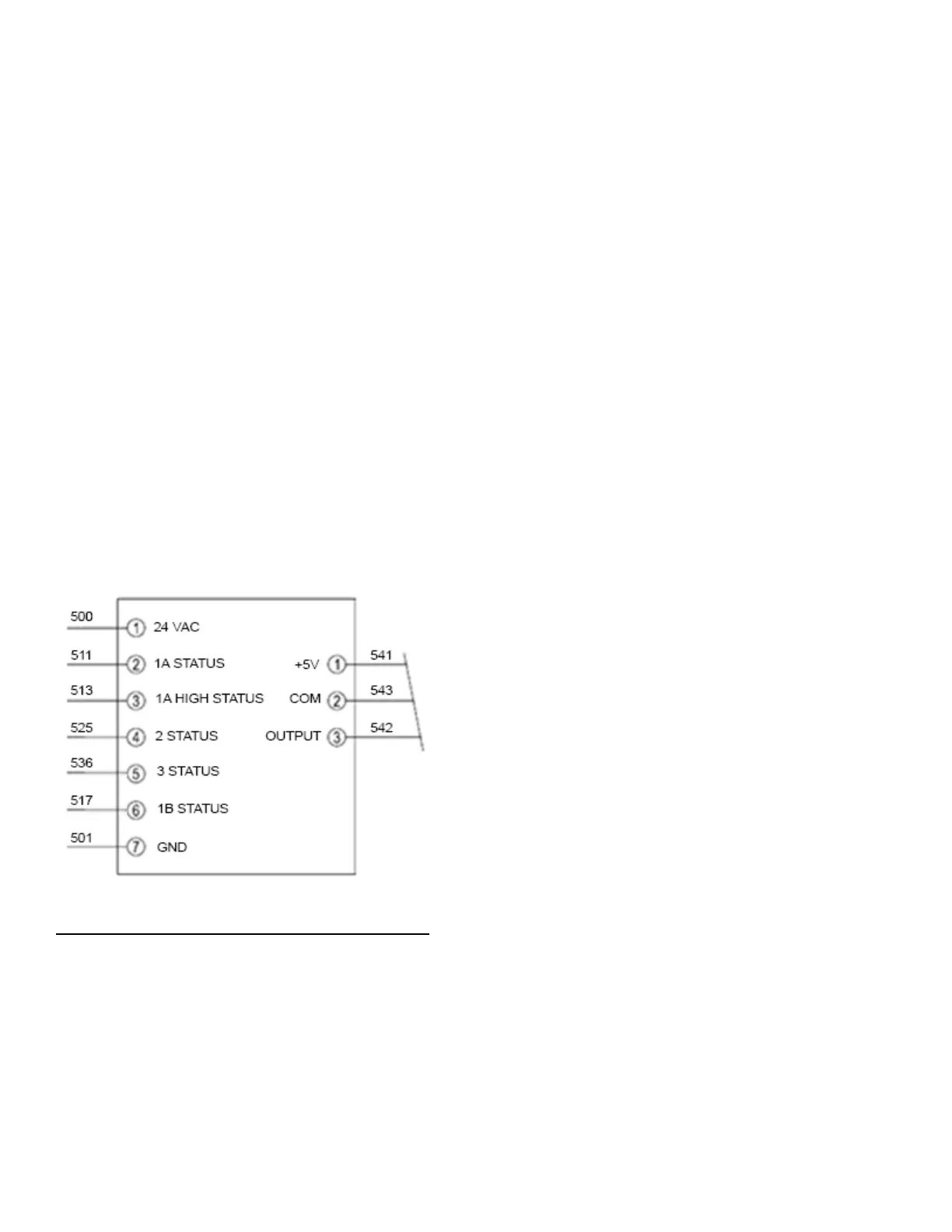
• Sends 24 VAC to the digital multiplexor con-
trol, which sends a 0–5 VDC signal back to
the IPU board. This 0–5 VDC signal proves
furnace 1A status is good.
• Once the IPU board receives the appropriate VDC
signal from the digital multiplexer control, the IPU
board removes 24 VAC from the 6R relay, which
causes:
1. The induced draft motor to switch to low speed
2. The modulating gas valve to switch to mini-
mum low fire
• Furnace 1A is now in Modulation mode.
• When ame rectication is not established, the ig-
nition control removes the high voltage spark and
24 VAC from the gas valve, waits 30 seconds, and
then tries again.
• The ignition sequence is tried three times. When a
ame is not established by the third try, the igni-
tion control locks out for 1 hour.
• Furnace sections 2, 3, and 1B follow the same se-
quence as staged gas heat.
LD21613
FIGURE 47 - DIGITAL MULTIPLEXOR
CONNECTIONS FOR MODULATING GAS HEAT
Modulating Operation
• Once Furnace 1A has successfully ignited, the
IPU board enters the normal modulating heat se-
quence.
• On a modulating gas heat unit. furnace 1A is al-
ways the rst ON and last OFF.
• Furnace 1A has a 2 stage gas valve and a modu-
lating gas valve controlled by a Maxitrol
®
Signal
Conditioner.
• The signal conditioner receives a 0–10 VDC sig-
nal from the IPU board depending on the required
heating demand.
1. Furnace 1A Low Fire
• Furnace 1A starts with the low fire solenoid of
the 2 stage gas valve being energized.
• Modulating gas valve at minimum position
at approximately 0.5–2 VDC from the IPU
board.
• The inducer motor is on low speed.
• When the heating demand increases, the
0–10 VDC signal increases, which further
opens the modulating valve.
• When the heating demand decreases, the
0–10 VDC signal decreases, which closes the
modulating gas valve.
• Modulating gas valve is at maximum posi-
tion at approximately 6.5 VDC from the IPU.
• When more heat is needed, furnace 1A
switches to high fire.
2. Furnace 1A High Fire
• The IPU energizes the high fire solenoid of
the 2 stage gas valve.
• Modulating gas valve at minimum position,
approximately 4–4.5 VDC from the IPU
board.
• The inducer motor switches to high speed.
• When the heating demand increases, the
0–10 VDC signal increases, which further
opens the modulating valve.
• When the heating demand decreases, the
0–10 VDC signal decreases, which closes the
modulating gas valve.