JOHNSON CONTROLS
82
FORM 100.50-NOM12
ISSUE DATE: 04/02/2019
SECTION 5 – SEQUENCE OF OPERATION
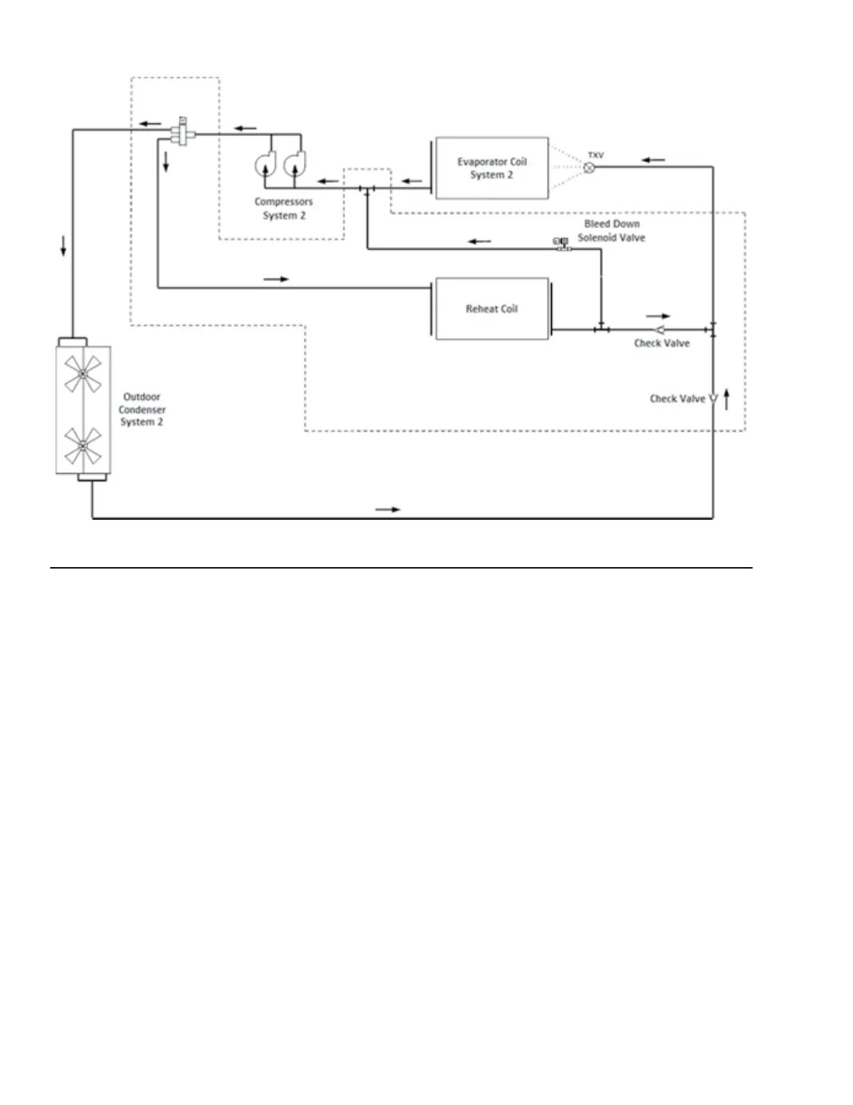
Modulating HGRH
3-Way Stepper
Valve
LD20880
FIGURE 40 - HGRH PIPING LAYOUT
• Units with HGRH have a combination SAT and
supply air humidity sensor installed.
• Units with HGRH have an evaporator leaving
air temperature sensor installed. This sensor uses
four sensors arranged in a averaging network.
HGRH Status
The HGRH system is shown in one of five states.
1. User Disabled
• The dehumidification control is set to User
Disabled either at the IPU board or through
a BAS command. HGRH operation is not al-
lowed
2. Inactive: The HGRH status is inactive when one
or more of the following requirements is met.
• The unit is not in an Active Cooling mode
• The OAT is less than 55.0°F
• Dehumidification is not required
• No Active HGRH Faults exist
HGRH Bleed Solenoid
• The HGRH bleed solenoid is powered by 24 VAC.
• The HGRH bleed solenoid is piped in between the
HGRH coil and the suction line for CKT 2.
• The valve bleeds off any remaining or trapped liq-
uid in the HGRH coil when HGRH is inactive.
• It is a normally closed valve that opens (energiz-
es) whenever HGRH is inactive.
• There is a 5 minute delay before opening the valve
after HGRH becomes inactive.
HGRH Setup
• HGRH is a factory installed option only available
on VAV and SZVAV congured units. No eld in-
stallation kits are available.
• HGRH operation must be set to Installed under
OPTIONS-UNIT DATA menu.
• Dehumidication control must be set to User En-
abled under PROGRAM-UNIT DATA menu.
• Units with HGRH have a combination RAT and
return air humidity sensor installed.