JOHNSON CONTROLS
87
SECTION 5 – SEQUENCE OF OPERATION
FORM 100.50-NOM12
ISSUE DATE: 04/02/2019
5
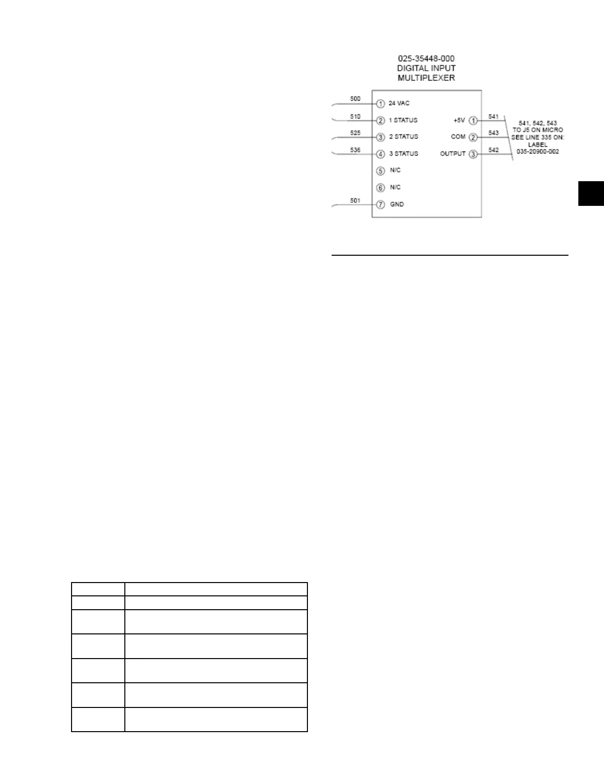
• Furnace status back to the IPU board is provided
through the multiplexor control.
• Each furnace is able to operate independently of
the other furnaces. This means if there is more
than one furnace section and one is faulted, the
others are still able to operate.
Staged Natural Gas Heat Setup
• Set the heating system type to staged gas under
the HEATING-OPTIONS menu.
• Set the gas heat capacity to the appropriate selec-
tion under the HEATING-OPTIONS menu.
• Ensure that the heating system is User Enabled
under the HEATING-PROGRAM menu.
1. S Z VAV
• 1st and 2nd stage heating setpoints must be
entered under the SETPOINTS-HEATING
menu.
• Occ and unocc zone heating setpoints must
be entered under the SETPOINTS-HEAT-
ING menu. This is only when zone control
method is set for wired or comm zone tem-
perature.
• If using Unocc mode, night set-back must be
User Enabled.
2. VAV
• RAT heating setpoint must be entered under
the SETPOINTS-HEATING menu.
• SAT heating setpoint must be entered under the
SETPOINTS-HEATING menu.
• For Unocc mode, the IPU board controls to
the unocc zone heating setpoint.
• For Unocc mode, night set-back must be
User Enabled.
TABLE 34 - STAGED GAS HEAT FURNACE STATUS
OFF No demand for heat
PURGE Induced draft motor is running for 30 seconds
TRY FOR
IGNITION
Ignition control is attempting to ignite the
burner (7 seconds)
ON-LOW
Furnace is operating normally in Low-Fire
mode
ON-HIGH
Furnace is operating normally in High-Fire
mode
FAULT
Ignition control did not prove ame, or other
safety switch opened
FAULT-
LOCKOUT
Multiplexor output to I/O board is not
accurate
LD28124
FIGURE 45 - DIGITAL MULTIPLEXOR
CONNECTIONS FOR STAGED GAS HEAT
Staged Gas Heat Sequence of Operation
• Once the IPU board determines there is a demand
for heat, a 24 VAC signal is sent to furnace 1.
• The inducer motor for furnace 1 starts and makes
the pressure switch.
• Once the pressure switch closes, 24 VAC runs
through two limit switches and back into the igni-
tion control. This lets the ignition control know
that all safety switches are closed.
• There is a 30 Second Purge Timer that allows the
inducer motor to ush the furnace with clean air.
• After the 30 Second Purge Timer expires, ignition
control simultaneously sends 24 VAC to the low
re solenoid of the gas valve and produces a high
voltage spark for 7 seconds to light the burners.
• Furnace 1 gas burners ignite.
• The ignition control monitors the ame signal for
15 seconds.
• After 15 seconds of steady ame rectication,
the ignition control sends 24 VAC to the digital
multiplexor control, which sends a 0–5 VDC sig-
nal back to the IPU board. This 0–5 VDC signal
proves furnace 1 status is good.
• When ame rectication is not established, the ig-
nition control removes the high voltage spark and
24 VAC from the gas valve, waits 30 seconds, and
then tries again.
• The ignition sequence is tried three times. When a
ame is not established by the third try, the igni-
tion control locks out for 1 hour.