JOHNSON CONTROLS
84
FORM 100.50-NOM12
ISSUE DATE: 04/02/2019
SECTION 5 – SEQUENCE OF OPERATION
HGRH Faults
• The HGRH Faults work to protect compressor
system 2 from damage as well as preventing un-
satisfactory temperature being delivered to the
space.
• The HGRH system has three faults that can occur:
Lockout HGRH 1, 2, or 3.
Lockout HGRH 1
The IPU board monitors the temperature difference
before and after the HGRH coil whenever HGRH is
inactive. When the HGRH valve is stuck OPEN, a tem-
perature rise occurs when it should not.
• HGRH is installed
• HGRH status is inactive
• Either compressor 2A or 2B is running
• The current SAT is 8.0°F higher than the current
evaporator air temperature
Lockout HGRH 2
The IPU board monitors the temperature difference be-
fore and after the HGRH coil whenever HGRH is ac-
tive. When the HGRH valve is stuck CLOSED, there is
no temperature rise when there should be.
• HGRH is installed
• HGRH status is active
• HGRH valve position is greater than 50%
• The current SAT is 8.0°F less than the current
evaporator air temperature
Lockout HGRH 3
The IPU board monitors the discharge pressure for
compressor system 2. When a compressor starts from
system 2, HGRH goes active, and there is a rapid rise
in discharge pressure, then the HGRH 3-way stepper
valve is blocked and not allowing refrigerant to flow to
either the HGRH coil or the condenser coil.
• HGRH is installed
• Either compressor 2A or 2B is running
• Compressor system 2 discharge pressure is greater
than 90% of the compressor system 2 unloading
pressure
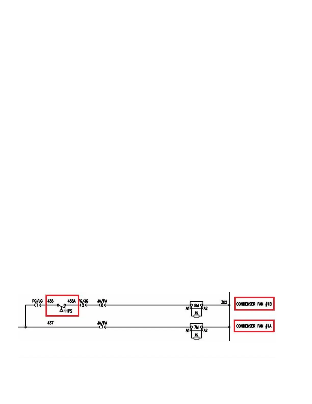
CONDENSER FAN CONTROL
• The Series 100 units have six condenser fans in-
stalled. There are two condenser fans for each
condenser section or “V.”
• All six condenser fans have their own contactor.
• The condenser fan A in each circuit starts when-
ever a compressor from that same circuit is started.
When condenser fan A has a condenser fan VFD
installed, the VFD is powered.
• The condenser fan B in each circuit is controlled by
a pressure switch. The pressure switch is wired in
series with the condenser fan B contactor.
• The pressure switch closes at 360 psig ± 10 psig
and opens at 240 psig ± 10 psig .
LD28122
FIGURE 43 - CONDENSER FAN CONTACTORS — FANS 1A AND 1B ONLY FOR COMPRESSOR SYSTEM #1