JOHNSON CONTROLS
49
SECTION 3 – START-UP
FORM 100.50-NOM12
ISSUE DATE: 04/02/2019
3
MANIFOLD PRESSURE – MODULATING GAS
TABLE 14 - LOW FIRE (INDUCER FAN ON LOW, 1.4"
W.C. INPUT TO MAXITROL VALVE)
INPUT VOLTAGE TO SIGNAL
CONDITIONER (VDC)
MANIFOLD
PRESSURE (“W.C.)
0.0 0.22
0.5 0.22
1.0 0.22
1.5 0.22
2.0 0.22
2.5 0.32
3.0 0.45
3.5 0.66
4.0 0.84
4.5 1.05
5.0 1.25
5.5 1.30
6.0 1.30
6.5 1.30
TABLE 15 - HIGH FIRE (INDUCER FAN ON HIGH,
3.5" W.C. INPUT TO MAXITROL VALVE)
INPUT VOLTAGE TO SIGNAL
CONDITIONER (VDC)
MANIFOLD PRESSURE
(“W.C.)
4.0 1.10
4.5 1.40
5.0 1.70
5.5 2.10
6.0 2.50
6.5 2.90
7.0 3.15
7.5 3.25
8.0 3.30
8.5 3.30
9.0 3.30
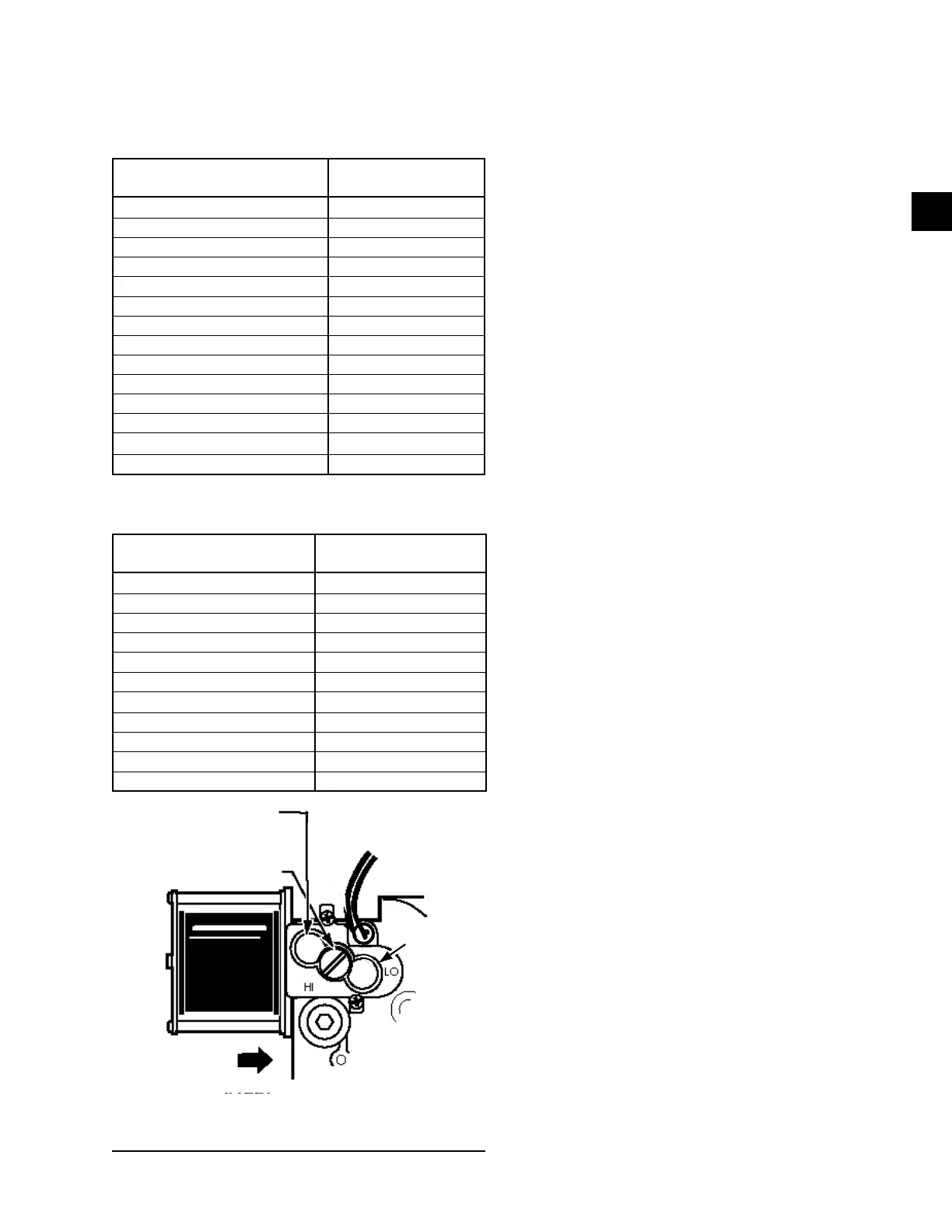
HIGH FIRE PRESSURE
REGULATOR
LOW FIRE
PRESSURE
REGULATO
TWO STAGE
PRESSURE
REGULATOR
REGULATOR VENT COVER
LD11760A
FIGURE 16 - MANIFOLD GAS PRESSURE
ADJUSTMENT
Manifold Gas Pressure Adjustment
Small adjustments to the manifold gas pressure can be
made by following the procedure outlined below. Refer
to Figure 16 on page 49 for the high and low fire
pressure regulator adjustment locations.
1. Turn the gas OFF to the unit.
2. Use a 3/16 inch Allen wrench to remove the 1/8
inch NPT plug from the outlet pressure tap of the
valve.
3. Install a brass adapter to allow the connection of a
hose to the outlet pressure tap of the valve.
4. Connect the hose to a manometer capable of read-
ing the required manifold pressure value.
5. Turn the gas back ON.
6. Place the heat section into high re operation.
7. Compare the high re manifold pressure to
Table 12 on page 48.
8. To adjust the high re manifold pressure remove
the cap from the high re pressure regulator. Use a
3/32 Allen wrench to make the manifold pressure
adjustment. To increase the manifold pressure,
turn the screw clockwise; to decrease the mani-
fold pressure, turn the screw counterclockwise.
Place your nger over the adjustment opening
while verifying the manifold pressure.
9. Place the heat section into low re operation.
10. Compare the low re manifold pressure to
Table 12 on page 48.
11. To adjust the low re manifold pressure remove
the cap from the low re pressure regulator. Use
a 3/32 inch Allen wrench to make the manifold
pressure adjustment. To increase the manifold
pressure, turn the screw clockwise; to decrease
the manifold pressure, turn the screw counter-
clockwise. Place your nger over the adjustment
opening while verifying the manifold pressure.
12. Turn the heat OFF.
13. Turn the gas OFF.
14. Remove the brass tubing adapter and replace the
plug in the outlet pressure tap.