JOHNSON CONTROLS
80
FORM 100.50-NOM12
ISSUE DATE: 04/02/2019
SECTION 5 – SEQUENCE OF OPERATION
• The HGRH system uses a 3-way stepper motor
to control the ow of discharge gas between the
condenser coil and the HGRH coil
• The HGRH system has a bled solenoid valve in-
stalled to allow oil drainage back into the com-
pressor
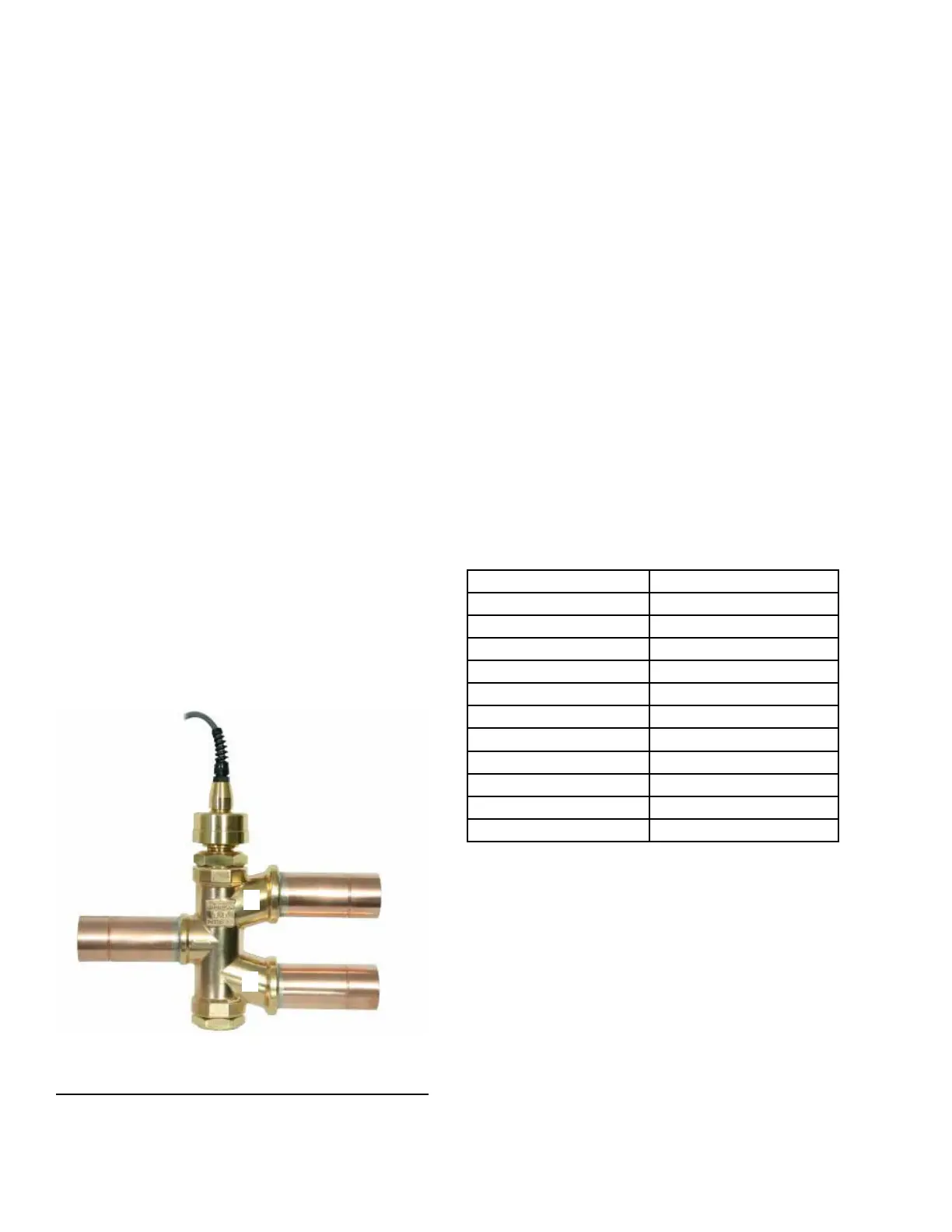
HGRH 3-Way Stepper Valve
• The HGRH system uses a 3-way stepper valve to
control the refrigerant ow between the condens-
er coil and the HGRH coil
• The 3-way stepper valve is a Sporlan
®
MTW-17
• The valve is controlled by a Sporlan IB-G inter-
face board
• The 3-way valve has a minimum and maximum
position whenever HGRH is active. These values
cannot be changed.
• Minimum: 25%
• Maximum: 95%
• See Figure 38 for 3-way stepper valve outputs/
inputs
• Outlet A is piped to the condenser coil
• Outlet B is piped to the HGRH coil
• Outlet C is piped from the discharge line
CKT 2
OUTLET B: TO HGRH COIL
OUTLET A: TO CONDENSER
COIL
FROM DISCHARGE
LINE CKT 2
B
A
LD20876
FIGURE 38 - HGRH 3-WAY STEPPER VALVE
HGRH Control Board
• The HGRH control board is factory installed and
programmed. No eld setup is required.
• The HGRH control board is powered by 24 VAC
• The HGRH control board receives a 0–10 VDC
signal from the IPU board. The HGRH control
board then sends pulse signals to the 3-way step-
per valve to modulate open/closed.
• TB9-11 and TB9-12 sends a 0–10 VDC signal
• The HGRH control board has three LEDs
• Red LED: This status LED is lit whenever
there is 24 VAC present
• Yellow LED: This closed LED is only lit
when the 3-way valve is fully closed
• Green LED: This valve open LED flashes in
different sequences depending on the valve
position
TABLE 30 - HGRH CONTROL BOARD GREEN LED
FLASH DESCRIPTIONS
NUMBER OF FLASHES VALVE POSITION % OPEN
1 Flash 0–10%
2 Flashes 10–20%
3 Flashes 20–30%
4 Flashes 30–40%
5 Flashes 40–50%
6 Flashes 50–60%
7 Flashes 60–70%
8 Flashes 70–80%
9 Flashes 80–90%
10 Flashes 90–99%
Remains Lit 100%