JOHNSON CONTROLS
35
SECTION 2 – INSTALLATION
FORM 100.50-NOM12
ISSUE DATE: 04/02/2019
2
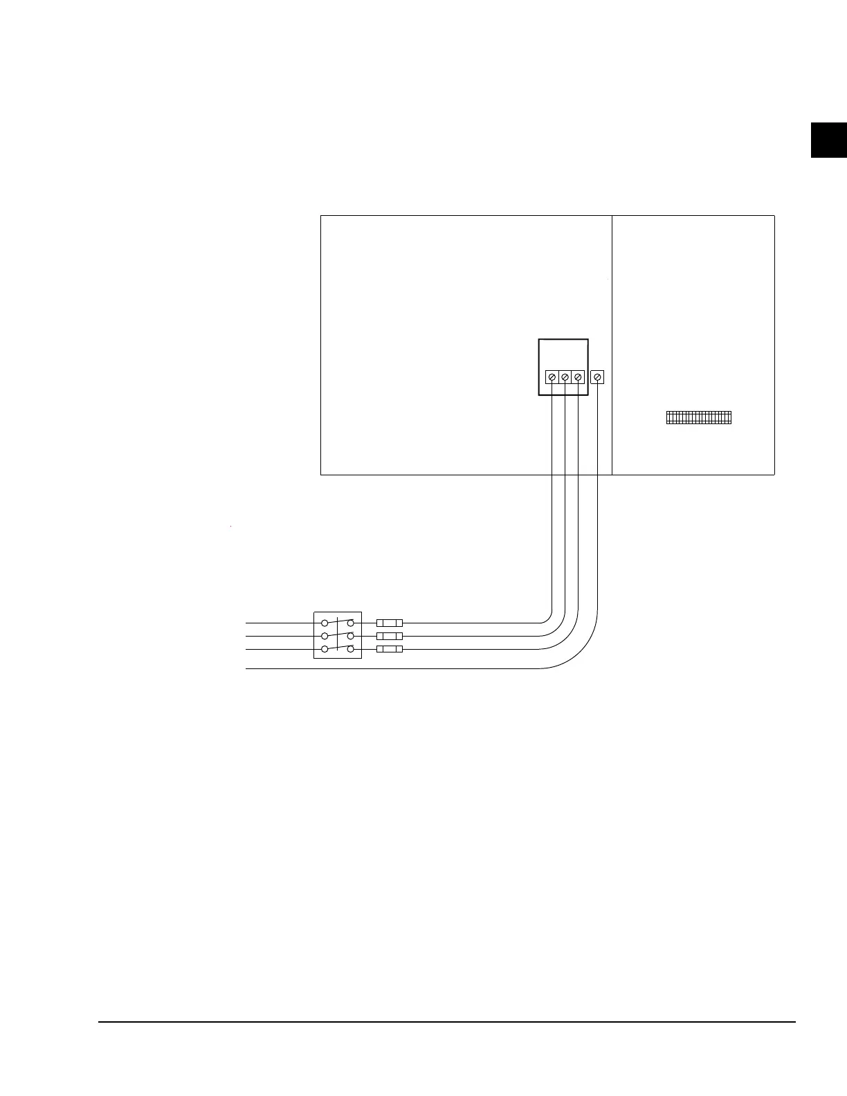
SINGLE-POINT POWER SUPPLY WIRING
WITH NON-FUSED DISCONNECT SWITCH
FIGURE 10 - SINGLE-POINT POWER SUPPLY WIRING WITH NON-FUSED DISCONNECT
NOTES:
1. All eld wiring must be provided through a eld-supplied fused disconnect switch to the unit terminals (or optional molded disconnect
switch).
2. All electrical wiring must be made in accordance with all N.E.C. and/or local code requirements.
3. Minimum Circuit Ampacity (MCA) is based on U.L. Standard 1995, Section 36.14 (N.E.C. Section 440-34).
4. Maximum Dual Element Fuse size is based on U.L. Standard 1995, Section 36.15 (N.E.C. Section 440-22).
5. Use copper conductors only.
6. On units with an optional disconnect switch, the supplied disconnect switch is a “Disconnecting Means” as dened in the N.E.C. Section
100, and is intended for isolating the unit from the available power supply to perform maintenance and troubleshooting. This disconnect
switch is not intended to be a Load Break Device.
CTB1
P ower S ide
F ield P ower
S upply
E arth
G round
Line 3
Line 2
Line 1
F ield C ontrol
Wiring T erminal
B lock
C ontrol S ide
1L1
1L2
1L3
G ND
E lectrical / C ontrols B ox
Molded
C ase
Disconnect
S witch
LD06415A