JOHNSON CONTROLS
74
FORM 100.50-NOM12
ISSUE DATE: 04/02/2019
SECTION 5 – SEQUENCE OF OPERATION
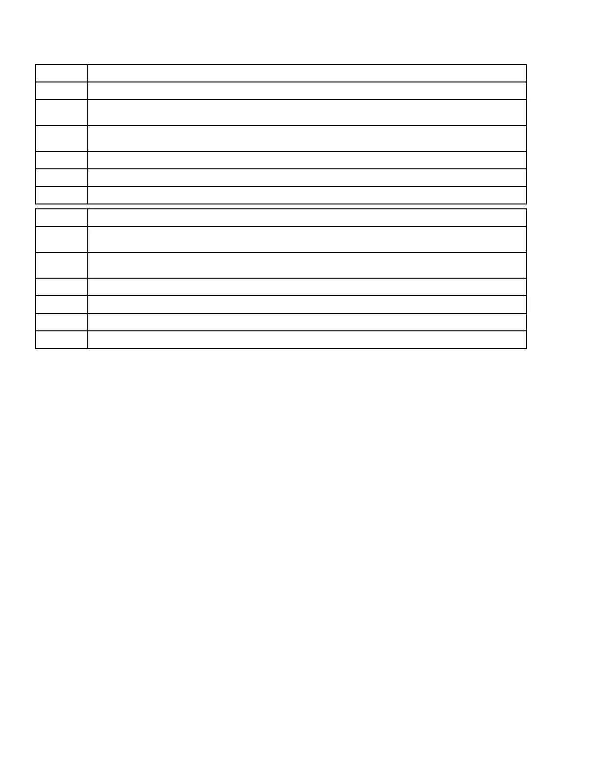
TABLE 27 - COMPRESSOR STAGING
STAGES STAGING ON
0 to 1 When both compressors 1A and 1B are ready to run, the IPU board turns ON the compressor with the fewest starts
1 to 2
When compressors 2A, 2B, 3A, and 3B are ready to run, the IPU board turns ON the compressor with the
fewest starts
2 to 3
The IPU board turns ON either the A or B compressor with the fewest starts from the remaining circuit that is
not yet active
3 to 4 The IPU board turns ON the inactive compressor from the circuit started in the stage 0 to 1 step
4 to 5 The IPU board turns ON the inactive compressor from the circuit started in the stage 1 to 2 step
5 to 6 The IPU board turns ON the inactive compressor from the circuit started in the stage 2 to 3 step
STAGES STAGING OFF
6 to 5
When compressors 3A, 3B, 2A, and 2B are all ready to stop, the IPU board turns OFF the compressor with the
fewest starts
5 to 4
Whichever circuit 2 or 3 still has two compressors operating, the IPU board turns OFF the compressor with the
fewest starts
4 to 3 Turn OFF compressor 1A or 1B, whichever has the fewest starts
3 to 2 Turn OFF a compressor from either circuit 2 or 3 that has the fewest starts
2 to 1 Turn OFF the last active compressor from either circuit 2 or 3
1 to 0 Turn OFF the active compressor from circuit 1
Fast Compressor Start
• The Series 100 unit's patented Fast Compressor Start
sequence stages ON compressors quickly when
switching from a Standby mode to a Cooling mode.
• Fast compressor start can be User Enabled/User
Disabled. It can be found under the PROGRAM-
UNIT DATA menu.
Fast Compressor Start is User Enabled
1. When the IPU board switches from a Standby
mode to a Cooling mode, it uses internal program-
ming logic to determine the correct stage of cool-
ing that is needed.
2. Once the correct stage is determined, the IPU board
stages ON compressors, with a 15 second time de-
lay in between, until the appropriate numbers of
compressors are operating.
3. Once the appropriate stage is reached, normal
compressor staging applies, with a 3.5 minute
time delay between compressor starts/stops.
4. One of the variables used in fast compressor start
is the unit design airow. This value needs to be
entered correctly for fast compressor start to work
properly. Unit design airow can be found in the
SETPOINTS-UNIT DATA menu.
Fast Compressor Start is User Disabled
• When the IPU board switches from a Standby
mode to a Cooling mode, it stages ON compres-
sors one at a time with the normal 3.5 minute time
delay between staging on a new compressor.
Compressor Operation
• The Series 100 units utilize scroll compressor
technology.
• The IPU board constantly monitors the compres-
sor safety circuit, LPCO switch, and suction line
temperature of a compressor circuit.
• The mechanical cooling lockout setpoint is
50.0°F. No compressor operation is allowed be-
low this temperature unless a low ambient pack-
age was ordered. Low ambient packages can be
ordered for one, two, or three systems.
• Each compressor circuit has a tandem set of com-
pressors piped together to a common suction and
discharge line. There is an oil equalization line be-
tween the two compressors.