JOHNSON CONTROLS
91
SECTION 5 – SEQUENCE OF OPERATION
FORM 100.50-NOM12
ISSUE DATE: 04/02/2019
5
• The modulating gas valve is at maximum
position at approximately 8–9 VDC from the
IPU board.
• When more heat is needed, the IPU board
brings on the next stage depending on the gas
heat capacity.
a. 375 MBH
• On a 375 MBH unit, there is only one
furnace section split into two halves: 1A
and 1B.
• Once furnace 1A has reached high fire
max position, furnace 1B is ignited.
• Furnace 1A stays on high fire but the
modulating valve is modulated between
minimum (4–4.5 VDC) and maximum
(8–9 VDC) positions.
b. 750 MBH
• On a 750 MBH unit, there are two fur-
nace sections.
• Furnace 1 is one section split into two
halves: 1A and 1B.
• Once furnace 1A has reached high fire
max position, furnace 2 is started on low
fire.
• Furnace 1A starts at low fire min and
goes through the low fire to high fire se-
quence as described above.
• When more heat is still needed, furnace
2 switches to high fire and furnace 1A
starts at low fire min and goes through
the low fire to high fire sequence as de-
scribed above.
• When more heat is needed and furnace
2 is on high fire and furnace 1A is at
high fire max, the IPU brings on furnace
1B and furnace 1A follows the sequence
listed under 375 MBH.
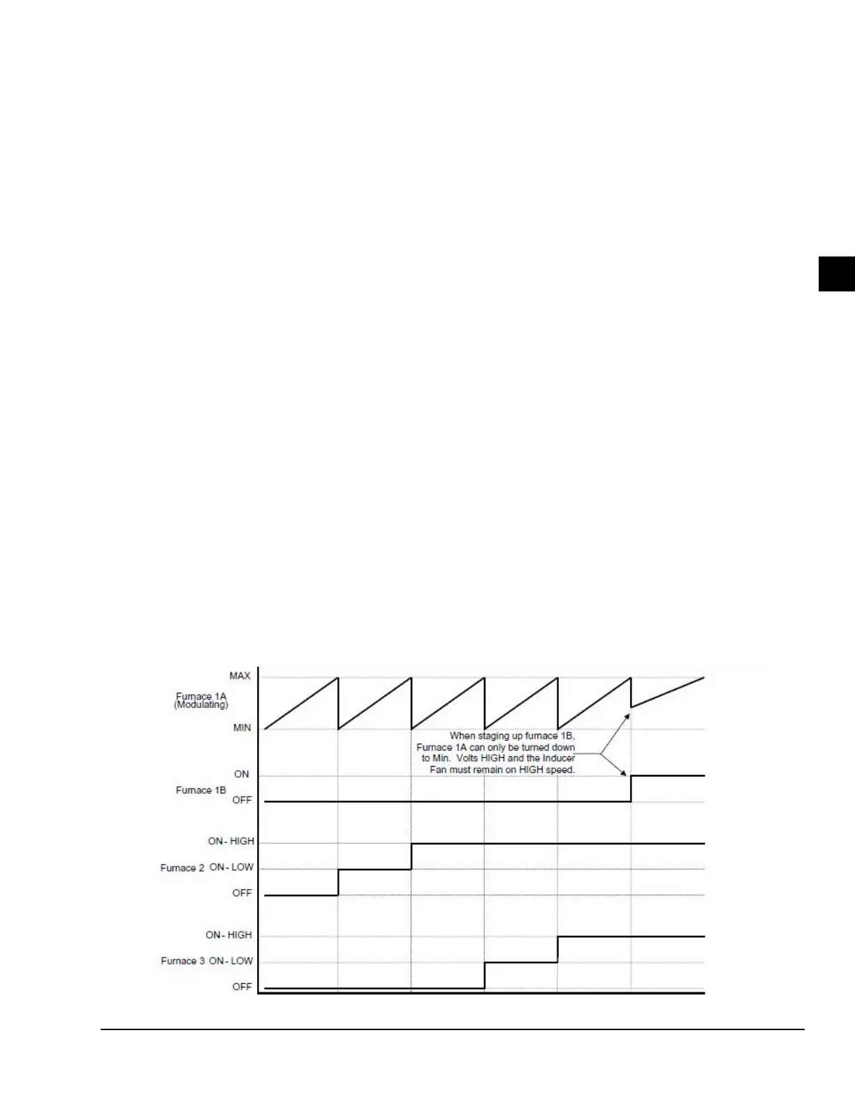
c. 1125 MBH
• On a 1125 MBH unit, there are three
furnace sections.
• Furnaces 1 and 2 are described as above.
• Furnace 3 is an exact match of furnace 2.
• Once Furnace 2 is at high fire,and fur-
nace 1A is at high fire max, furnace 3 is
started on low fire.
• The same sequence is followed on fur-
nace 3 and furnace 1A and 1B as listed
above in the 750 MBH sequence.
• Furnace 2 remains at high fire during
the furnace 3 sequence as long as the
heating demand keeps increasing.
LD10151
FIGURE 48 - MODULATING GAS HEAT STAGING SEQUENCE