JOHNSON CONTROLS
39
SECTION 2 – INSTALLATION
FORM 100.50-NOM12
ISSUE DATE: 04/02/2019
2
GAS HEATING
Gas Piping
Proper sizing of the gas piping depends on the cubic
feet per hour of gas flow required, specific gravity of
the gas and the length of run. The latest edition of the
National Fuel Gas Code Z223.1 should be followed in
all cases unless superseded by local codes or gas com-
pany requirements. Refer to Table 10 on page 39.
TABLE 10 - PIPE SIZES
LENGTH IN
FEET
NOMINAL IRON PIPE SIZE
1-1/2 IN.
1
2 IN.
1
10 1,600 3,050
20 1,100 2,100
30 890 1,650
40 760 1,450
50 1,270
60 1,150
70 1,050
80 990
1
Maximum capacity of pipe in cubic feet of gas per hour (based
upon a pressure drop of 0.3 i" W.C. and 0.6 specic gravity gas).
The heating value of the gas may differ with locality.
The value should be checked with the local gas utility.
There may be a local gas utility require-
ment specifying a minimum diameter for
gas piping. All units require a 1 1/2-inch
pipe connection at the entrance tting.
Line size should not be sized smaller than
the entrance tting size.
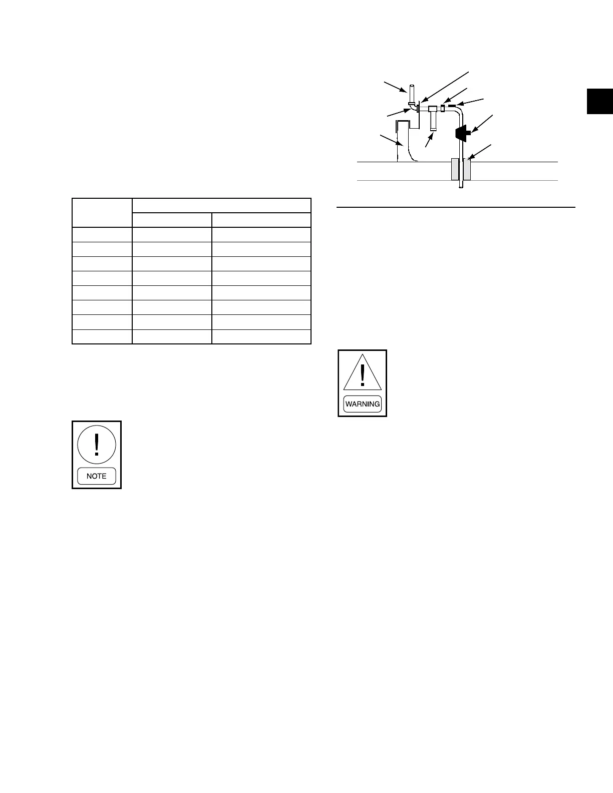
Gas Connection
The gas supply line should be routed within the space
and penetrate the roof at the gas inlet connection of the
unit. Many local codes require that a shut off valve be
located external to the unit. In these cases it is easier to
run the gas piping on the roof and enter the unit through
the side of the base rail. Typical supply piping arrange-
ments are shown in Figure 13 on page 39.
FIGURE 13 - TYPICAL GAS PIPING CONNECTION
1-1/2" FPT
FACTORY
PIPING
ROOF
CURB
DRIP LEG
UNIT BASERAIL
UNION (For Servicing)
1/8" NPT PLUG
MANUAL GAS
VALVE
PITCH POCKET
ROOF
LD11765A
Gas Piping Recommendations
1. A drip leg and a ground joint union must be in-
stalled in the gas piping.
2. When required by local codes, a manual shut-off
valve has to be installed outside of the unit.
3. Use wrought iron or steel pipe for all gas lines.
Pipe dope should be applied sparingly to male
threads only.
Natural gas may contain some propane.
Propane being an excellent solvent will
quickly dissolve white lead or most stan-
dard commercial compounds. Therefore,
a special pipe dope must be applied when
wrought iron or steel pipe is used. Shel-
lac base components such as Gaskolac
or Stalastic, and compounds such as
Rectorseal #5, Clyde’s or John Crane
may be used.
4. All piping should be cleaned of dirt and scale by
hammering on the outside of the pipe and blow-
ing out the loose particles. Before initial start-up,
be sure that all of the gas lines external to the unit
have been purged of air.
5. The gas supply should be a separate line and in-
stalled in accordance with all safety codes as
prescribed under “Limitations” listed in the be-
ginning of SECTION 2 – INSTALLATION of this
manual. After the gas connections have been com-
pleted, open the main shutoff valve admitting gas
pressure to the mains. Check all joints for leaks
with soap solution or other material suitable for
the purpose. NEVER USE A FLAME!
6. The furnace and its individual manual shut-off
valve must be disconnected from the gas supply
piping system during any pressure testing of that
system at test pressures in excess of 0.5 PSIG.