JOHNSON CONTROLS
42
FORM 100.50-NOM12
ISSUE DATE: 04/02/2019
SECTION 3 – START-UP
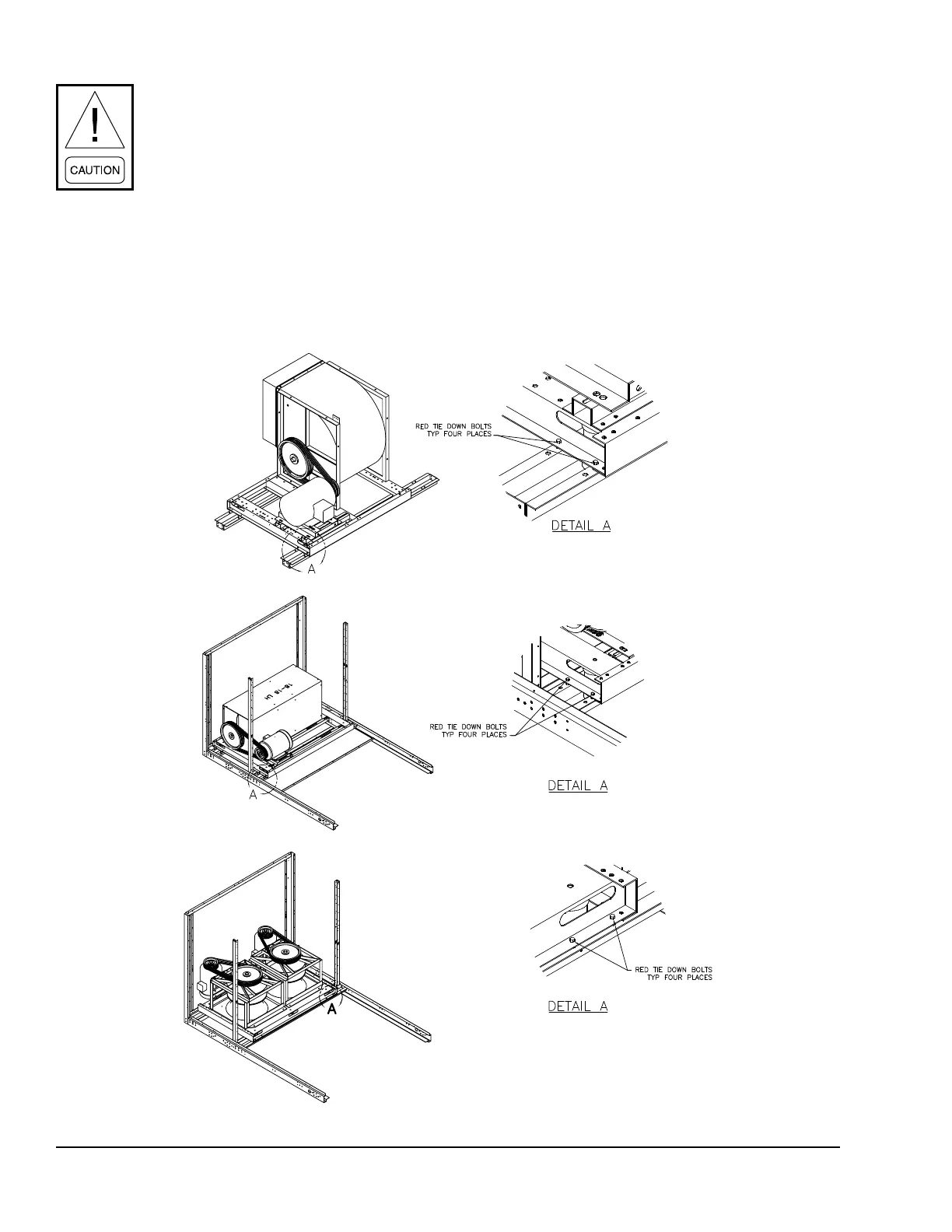
The supply, exhaust and return fans have
tie down bolts installed at the factory to
prevent movement in the fan assemblies
during shipment. THESE HOLD DOWN
BOLTS MUST BE REMOVED PRIOR
TO OPERATION OF THE ABOVE
FANS. There are eight bolts per assembly
two at each comer of the fan skids, front
and rear. The bolt locations are shown
in Figure 15. The bolt heads are red in
color and a label identies their location
in the unit.
13. Verify proper belt tension of supply fan, exhaust
fan or return fan (refer to SECTION 4 – MAINTE-
NANCE of this manual). Belts must be checked
after 24 hours of initial operation.
14. Manually rotate condenser fan blades, supply ex-
haust and return blower wheels and motors, to as-
sure freedom of movement.
15. Verify proper condensate drain trap installation
(refer to Figure 15 on page 42). Fill traps with
water prior to unit start-up.
RETURN FAN ASSEMBLY
SUPPLY FAN ASSEMBLY
EXHAUST FAN ASSEMBLY
LD11448
FIGURE 15 - FAN ISOLATOR SPRING BOLTS (TOTAL OF 8)