JOHNSON CONTROLS
54
FORM 100.50-NOM12
ISSUE DATE: 04/02/2019
SECTION 4 – MAINTENANCE
Forward Curved Fans
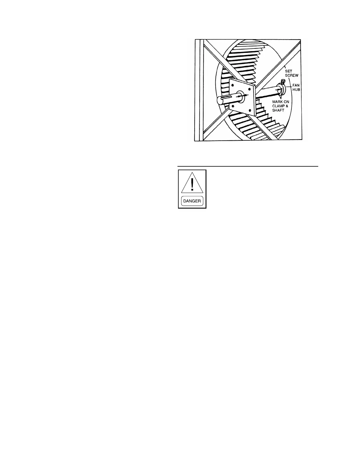
The forward curved fan wheel must be removed
through the fan discharge opening. The location of
other clamps, fan wheel, and shaft must be marked so
each of these components can be reassembled in the
same location (see Figure 20 on page 54). This will
preserve the balance of the rotating assembly. Proceed
with the following steps:
1. Disconnect all duct work or guards attached to the
blower housing to permit unobstructed access.
2. Remove the cut off plate attached at the discharge
or blast area of the blower housing.
3. Thoroughly clean the shaft of all grease and rust
inhibitor. Be careful not to contaminate the bear-
ing grease. Use emery cloth to remove all rust or
the wheel may become “locked” to the shaft.
4. Loosen and remove set screws on both bearing
locking collars. Inspect and, if necessary, replace.
5. Loosen and remove set screws from both sides of
the wheel hub. Inspect and, if necessary, replace.
6. Using a rubber mallet or brass bar, slowly drive the
shaft in one direction until the set screw marks on
the shaft are fully exposed. File the marks com-
pletely smooth. Drive the shaft in the opposite di-
rection and le smooth the set screw marks. Con-
tinue to clean the shaft of all dirt and residuals.
7. To remove the key, use a rubber mallet or brass
bar to drive the shaft and wheel in one direction.
Drive the key in the opposite direction using a nail
set or smaller size key stock until the key is com-
pletely free of the wheel. Be sure that key does
not get bent by allowing it to ride up the key way
edge. The slightest bend will prevent quick as-
sembly. Should this occur, replace the key stock.
8. Remove the shaft, supporting the weight of the
wheel, particularly for larger diameter wheels. Do
not allow the weight of the shaft to be supported
by one bearing as you disassemble.
9. Remove the wheel through the discharge or outlet
area of the blower housing.
10. Reassemble in reverse order, centering the wheel
between the edges of the inlet venturi. If bearings
were removed or replaced, be sure to reuse any
shim stock found between the mounting support/
plate and bearing housings.
11. Torque all hardware.
LD06355
FIGURE 20 - FORWARD CURVED FAN SHAFT/
WHEEL MARKING
Disconnect and lock-out power from the
unit anytime service is being performed
on the fan section. Failure to do so could
result in serious injury or death due to the
fan turning ON while work is in progress.
Fan Motor
1. Shut OFF unit power and lock out.
2. Disconnect and tag power wires at motor
terminals.
3. Loosen motor base-to-mounting-rail attaching
bolts.
4. Mark belt as to position. Remove and set aside
belts.
5. Remove motor bracket hold down bolts.
6. Remove motor pulley and set aside.
7. Remove motor.
8. Install new motor. Reassemble by reversing steps
1–6. Be sure to reinstall multiple belts in their
original position. Use a complete new set if re-
quired. Do not stretch belts over sheaves. Review
the sections on motor and sheave installation,
sheave alignment, and belt tensioning discussed
previously in this manual.
9. Reconnect motor leads and restore power. Check
fan for proper rotation as described in the Series
100 Start-Up Checklist (Form 100.50-CL2).