JOHNSON CONTROLS
89
SECTION 5 – SEQUENCE OF OPERATION
FORM 100.50-NOM12
ISSUE DATE: 04/02/2019
5
LD28125
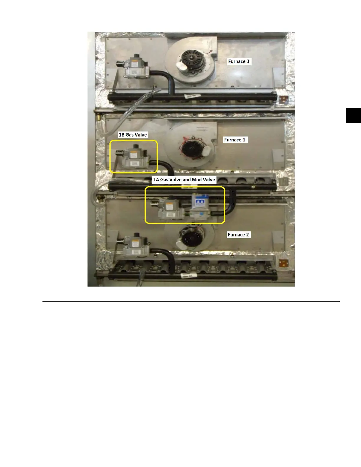
FIGURE 46 - MODULATING GAS FURNACE SECTIONS
Modulating Gas Heat Sequence of Operation
• Once the IPU board determines there is a demand
for heat, a 24 VAC signal is sent to furnace 1A.
• At the same time, the IPU board sends a 24 VAC
signal to the 6R (1A high re relay).
• The inducer motor for furnace 1A starts on high
speed and make both the low and high pressure
switches.
• Once the pressure switches close, 24 VAC runs
through two limit switches and back into the igni-
tion control. This lets the ignition control know
that all safety switches are closed.
• There is a 30 Second Purge Timer that allows the
inducer motor to ush the furnace with clean air.
• After the 30 Second Purge Timer expires, the igni-
tion control:
1. Sends 24 VAC to the low and high fire so-
lenoid of the gas valve and produces a high
voltage spark for 7 seconds.
2. Modulates the modulating gas valve to mini-
mum high fire.
• Furnace 1A gas burners ignite.
• The ignition control monitors the ame signal for
15 seconds.
• After 15 seconds of steady ame rectication, the
ignition control: