EasyManuals Logo

Johnson Controls 100 Series User Manual

Johnson Controls 100 Series
182 pages
To Next Page IconTo Next Page
To Previous Page IconTo Previous Page
Page #32 background imageLoading...
Page #32 background image
JOHNSON CONTROLS
32
FORM 100.50-NOM12
ISSUE DATE: 04/02/2019
SECTION 2 – INSTALLATION
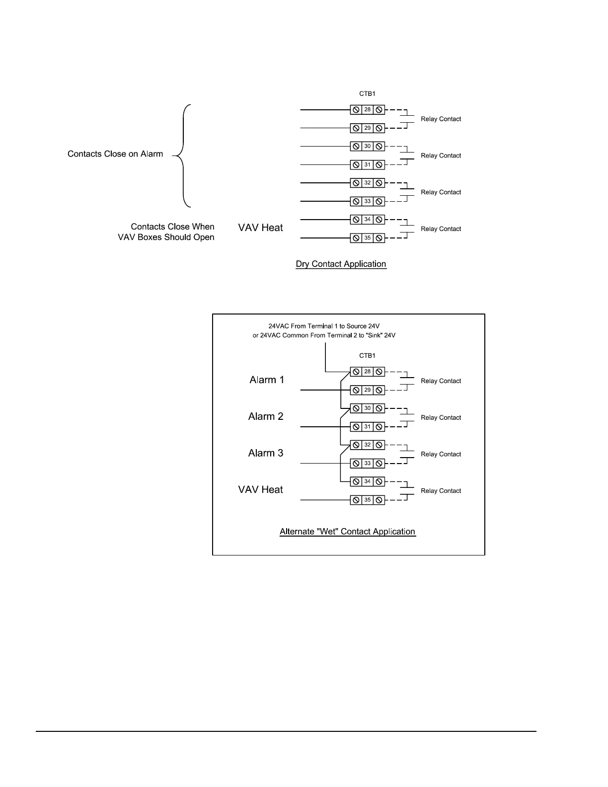
FIGURE 8 - FIELD CONTROL WIRING - OUTPUTS
Supply Fan Fault
Cooling/Heating Fault
Sensor Misc. Fault
AL1C
AL3C
AL3
HRC
HR
AL2C
AL2
AL1
AL1
AL2
AL3
HR
ld08186C
WIRING NOTES:
1. Wiring shown indicates typical wiring. Refer to the IOM for more detailed wiring methods and options.
2. All wiring is Class 2, low voltage.
3. Maximum power available from the 24VAC terminal is 40VA.
4. Use shielded wire where shown.
5. Relay contacts suitable for pilot duty to 1A from 24VAC to 120VAC.
CTB1 FIELD CONTROL WIRING (OUTPUTS)

Table of Contents

Other manuals for Johnson Controls 100 Series

Questions and Answers:

Question and Answer IconNeed help?

Do you have a question about the Johnson Controls 100 Series and is the answer not in the manual?

Johnson Controls 100 Series Specifications

General IconGeneral
BrandJohnson Controls
Model100 Series
CategoryAir Conditioner
LanguageEnglish

Related product manuals