JOHNSON CONTROLS
26
FORM 100.50-NOM12
ISSUE DATE: 04/02/2019
SECTION 2 – INSTALLATION
ELECTRICAL DATA
Electrical Service Sizing
In order to use the electrical service required for the
cooling-only Packaged Rooftop Unit, use the appropri-
ate calculations listed below from U.L. 1995. Based on
the configuration of the rooftop, the calculations will
yield different MCA (minimum circuit ampacity), and
MOP (maximum overcurrent protection).
Using the following load definitions and calculations,
determine the correct electrical sizing for your unit. All
concurrent load conditions must be considered in the
calculations, and you must use the highest value for
any combination of loads.
Load Definitions
• LOAD1 is the current of the largest motor – com-
pressor or fan motor.
• LOAD2 is the sum of the remaining motor cur-
rents that may run concurrently with LOAD
• LOAD3 is the current of the electric heaters –
zero for cooling only units.
• LOAD4 is the sum of any remaining currents
greater than or equal to 1.0 amp.
Use the following calculations to determine MCA
and MOP for units supplied with a single-point power
connection:
MCA = (1.25 x LOAD1) + LOAD2 + LOAD3 + LOAD4
MOP = (2.25 x LOAD1) + LOAD2 + LOAD3 + LOAD4
If the MOP does not equal a standard current rating
of an overcurrent protective device, then the marked
maximum rating is to be the next lower standard rating.
However, if the device selected for MOP is less than
the MCA, then select the lowest standard maximum
fuse size greater than or equal to the MCA.
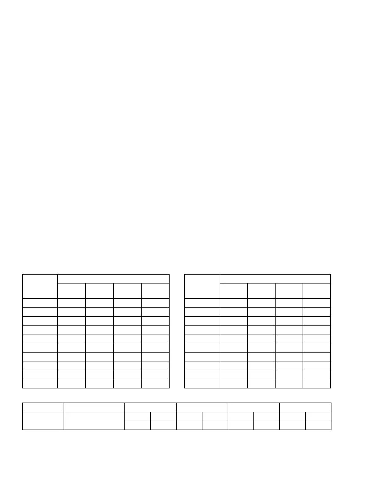
TABLE 4 - SUPPLY, EXHAUST, RETURN FAN MOTOR DATA
PREMIUM EFFICIENCY - ODP
MOTOR HP
NOMINAL VOLTAGE
208/3/60
FLA
230/3/60
FLA
460/3/60
FLA
575/3/60
FLA
5 14.0 13.2 6.6 5.3
7.5 20.4 19.4 9.7 8.0
10 26.0 25.0 12.5 10.0
15 38.0 36.0 18.0 14.2
20 52.0 48.0 24.0 18.9
25 64.0 60.0 30.0 24.5
30 76.0 72.0 36.0 28.0
40 99.0 98.0 49.0 40.0
50 121.0 114.0 57.0 46.0
60 144.0 136.0 68.0 56.0
PREMIUM EFFICIENCY - TEFC
MOTOR HP
NOMINAL VOLTAGE
208/3/60
FLA
230/3/60
FLA
460/3/60
FLA
575/3/60
FLA
5 13.9 13.4 6.7 5.3
7.5 20.0 19.0 9.5 7.6
10 25.4 24.0 12.0 9.6
15 38.0 36.2 18.1 14.6
20 52.0 48.0 24.0 19.2
25 64.0 62.0 31.0 24.0
30 78.0 76.0 38.0 24.0
40 102.0 96.0 48.0 37.0
50 128.0 116.0 58.0 45.0
60 149.0 135.0 67.8 54.4
TABLE 5 - CONDENSER FAN MOTOR DATA
MODEL QUANTITY OF FANS 208V/3PH/60HZ 230V/3PH/60HZ 460V/3PH/60HZ 575V/3PH/60HZ
YPAL070–105 6
RLA FLA RLA FLA RLA FLA RLA FLA
7.3 43.8 6.2 37.2 3.1 18.6 2.5 15.0
NOTE: RLA data is per condenser fan motor.