JOHNSON CONTROLS
105
SECTION 5 – SEQUENCE OF OPERATION
FORM 100.50-NOM12
ISSUE DATE: 04/02/2019
5
• The BAS sends a 0–100% command to the IPU
board (BACnet point AV52).
• Once the BAS command is greater than the ex-
haust output for fan start, the exhaust fan VFD is
started.
• Once the BAS command is less than the xhaust
output for fan stop, the exhaust fan VFD is
stopped.
Return Fan Assembly
• The Series 100 unit can be ordered with an op-
tional return fan assembly.
• The return fan assembly can be ordered as either
return fan without exhaust or return fan with ex-
haust.
• A return fan assembly is typically used on systems
where the return duct static pressure is greater
than 0.75 iwg.
• A return fan assembly assists the supply fan in
drawing the proper amount of return air from the
building.
• The return fan runs whenever the supply fan is
ON.
• On the Series 100 units, the return fan assembly
has one VFD controlling two separate return fan
assemblies.
• When operating properly, the return fan assem-
blies are spinning in opposite directions.
Return Fan without Exhaust Sequence of
Operation
• Power exhaust type must be set to Return Fan
without Exhaust in the OPTIONS-EXHAUST
menu.
• The return fan speed is controlled by the active
return fan plenum pressure setpoint.
• In this sequence, the return plenum pressure
setpoint is a xed value of 0.05 iwg.
• When the supply fan starts, the return fan starts
as well.
• The IPU board monitors the return fan plenum pres-
sure and controls the speed of the return fan VFD
up/down to maintain the return fan plenum pressure
setpoint.
Return Fan with Exhaust Sequence of
Operation
• Power exhaust type must be set to Return Fan
with Exhaust in the OPTIONS-EXHAUST menu.
• Building pressure setpoint must be set in the SET-
POINTS-EXHAUST menu.
• Return pressure high setpoint must be set in the
SETPOINTS-SUPPLY SYSTEM menu.
• The return fan speed is controlled by the active
return fan plenum pressure setpoint.
• When the supply fan starts, the return fan starts
as well.
• The return fan speed is controlled as follows:
1. Building pressure less than the building pres-
sure setpoint
• The return fan speed is controlled to the
fixed return plenum pressure setpoint of
0.05 iwg.
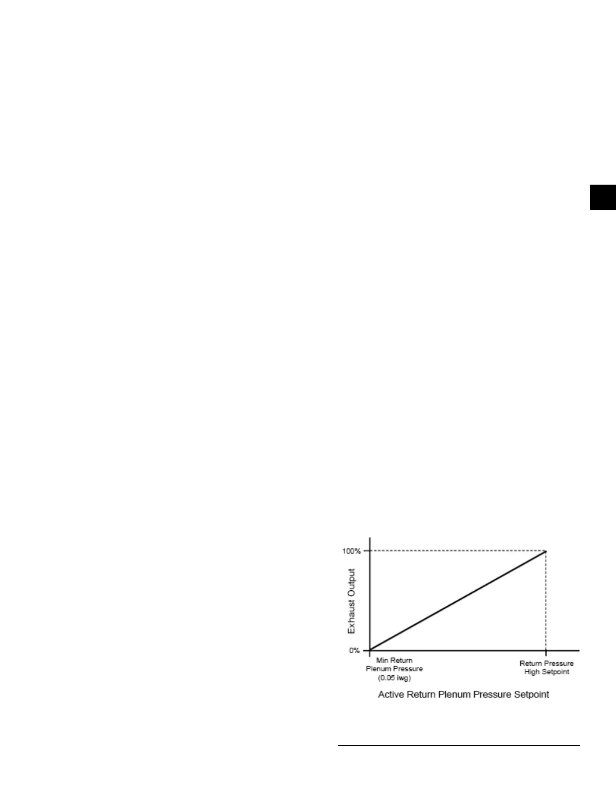
2. Building pressure greater than the building
pressure setpoint:
• The return fan speed is controlled to the
active return plenum pressure setpoint.
• As the building pressure rises above the
building pressure setpoint, the Active
return plenum pressure setpoint starts to
reset to a higher value.
• When the exhaust demand reaches 100%,
the active return plenum pressure setpoint
is equal to the return pressure high
setpoint. See Figure 55 on page 105.
LD28131
FIGURE 55 - ACTIVE RETURN PLENUM PRESSURE
SETPOINT VERSUS EXHAUST OUTPUT

 Loading...


