JOHNSON CONTROLS
93
SECTION 5 – SEQUENCE OF OPERATION
FORM 100.50-NOM12
ISSUE DATE: 04/02/2019
5
• The 24 VAC inputs are provided from the V1
terminals of the ignition controls, except for
the 1A high, which is provided when the PS2
pressure switch closes. PS2 pressure switch
closes when the induced draft motor on fur-
nace section 1 is on high speed.
• 24 VAC must be present at TB1-1 and TB1-7
for the multiplexer to function properly. DS1
LED is lit when 24 VAC is present at TB1-1
and TB1-7.
2. TB2 and LED Light DS7
• TB2 is used to output a 0–5 VDC signal back
to the IPU board.
• TB2 outputs on staged and modulating gas
heat:
• TB2-1: 5 VDC power from IPU board
• TB2-2: 5 VDC common to IPU board
• TB2-3: 0–5 VDC signal back to IPU
board
• 5 VDC must be present at TB2-1 and TB2-2
for the multiplexer to function properly. DS7
LED is lit when 5 VDC is present at TB2-1
and TB2-2.
• When 5 VDC is not present at TB2-1 and
TB2-2, neither DS1 or DS7 are lit.
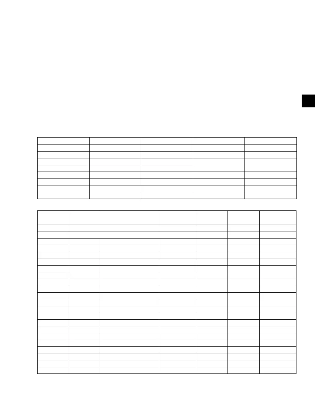
TABLE 36 - STAGED GAS HEAT 0–5 VDC OUTPUTS TO IPU
MIN VOLTS DC MAX VOLTS DC FURNACE 1 STATUS FURNACE 2 STATUS FURNACE 3 STATUS
0.086 0.166 OFF OFF OFF
0.224 0.313 ON OFF OFF
0.361 0.461 OFF ON OFF
0.499 0.609 ON ON OFF
0.637 0.756 OFF OFF ON
0.774 0.904 ON OFF ON
0.912 1.051 OFF ON ON
1.050 1.199 ON ON ON
TABLE 37 - MODULATING GAS HEAT 0–5 VDC OUTPUTS TO IPU
MIN VOLTS
DC
MAX
VOLTS DC
MODULATING
FURNACE 1A STATUS
FURNACE 1A
STATUS
FURNACE 2
STATUS
FURNACE 3
STATUS
FURNACE 1B
STATUS
0.086 0.166 OFF OFF OFF OFF OFF
0.224 0.313 ON OFF OFF OFF OFF
0.361 0.461 OFF ON OFF OFF OFF
0.499 0.609 ON ON OFF OFF OFF
0.637 0.756 OFF OFF ON OFF OFF
0.774 0.904 ON OFF ON OFF OFF
0.912 1051 OFF ON ON OFF OFF
1.050 1.199 ON ON ON OFF OFF
1.187 1.346 OFF OFF OFF ON OFF
1.325 1.494 ON OFF OFF ON OFF
1.463 1.641 OFF ON OFF ON OFF
1.600 1.789 ON ON OFF ON OFF
1.738 1.936 OFF OFF ON ON OFF
1.876 2.084 ON OFF ON ON OFF
2.013 2.231 OFF ON ON ON OFF
2.151 2.379 ON ON ON ON OFF
2.289 2.526 OFF OFF OFF OFF ON
2.426 2.674 ON OFF OFF OFF ON
2.564 2.821 OFF ON OFF OFF ON
2.702 2.969 ON ON OFF OFF ON
2.839 3.116 OFF OFF ON OFF ON
2.977 3.264 ON OFF ON OFF ON