JOHNSON CONTROLS
63
SECTION 5 – SEQUENCE OF OPERATION
FORM 100.50-NOM12
ISSUE DATE: 04/02/2019
5
• When the unit has a heating source installed:
• Occ zone heating setpoint must be set in the
SETPOINTS-HEATING menu (zone control
method is wired or Comm Zone Temperature).
• 1st and 2nd stage heating setpoints must be
set in the SETPOINTS-HEATING menu.
• The IPU board must have a valid zone temperature
reading if zone control method is set to Wired or
Comm Zone Temperature.
Supply Fan
• The supply fan must be running before any other
unit operation is allowed.
• The IPU board monitors the status of an APS to de-
termine the supply fan status.
• The APS must be closed, which proves supply fan
status before cooling, heating, or any other operation
is permitted.
• The supply fan is started whenever there is a de-
mand for cooling or heating, regardless of occu-
pancy.
• The supply fan can be operated continuously in
the Occ mode if continuous ventilation is User En-
abled in the PROGRAM-VENTILATION menu.
• The supply fan is started if zone control method is
set to Staged and there is a demand for G terminal
either from a thermostat or from the BAS.
Supply Fan Status
• The unit uses an APS to determine supply fan sta-
tus.
• The APS is a diaphragm type switch that closes at
approximately 0.30 iwg.
• The APS is mounted above the supply fan blower
assembly.
• The APS senses the static pressure through a fac-
tory installed tube that passes through the supply
fan wall into the next section of the unit.
• The APS needs to close and prove supply fan sta-
tus within 45 seconds after the supply fan is com-
manded on.
• Failure to prove supply fan status within 45 sec-
onds causes a Supply Fan Lockout to occur.
• A Supply Fan Lockout also occurs when the APS
opens for more than 2 seconds after fan status is
proven to be running.
As per ASHRAE 90.1-2010, Series 100 units has a
supply fan VFD installed to control the speed of the
supply fan based on cooling/heating demands or stand-
by operation when configured for SZVAV.
SZVAV Minimum Speed
• User adjustable setpoint that can be found under
SETPOINTS-SUPPLY SYSTEM menu.
• This is the speed the supply fan operates at per
Table 21 on page 63.
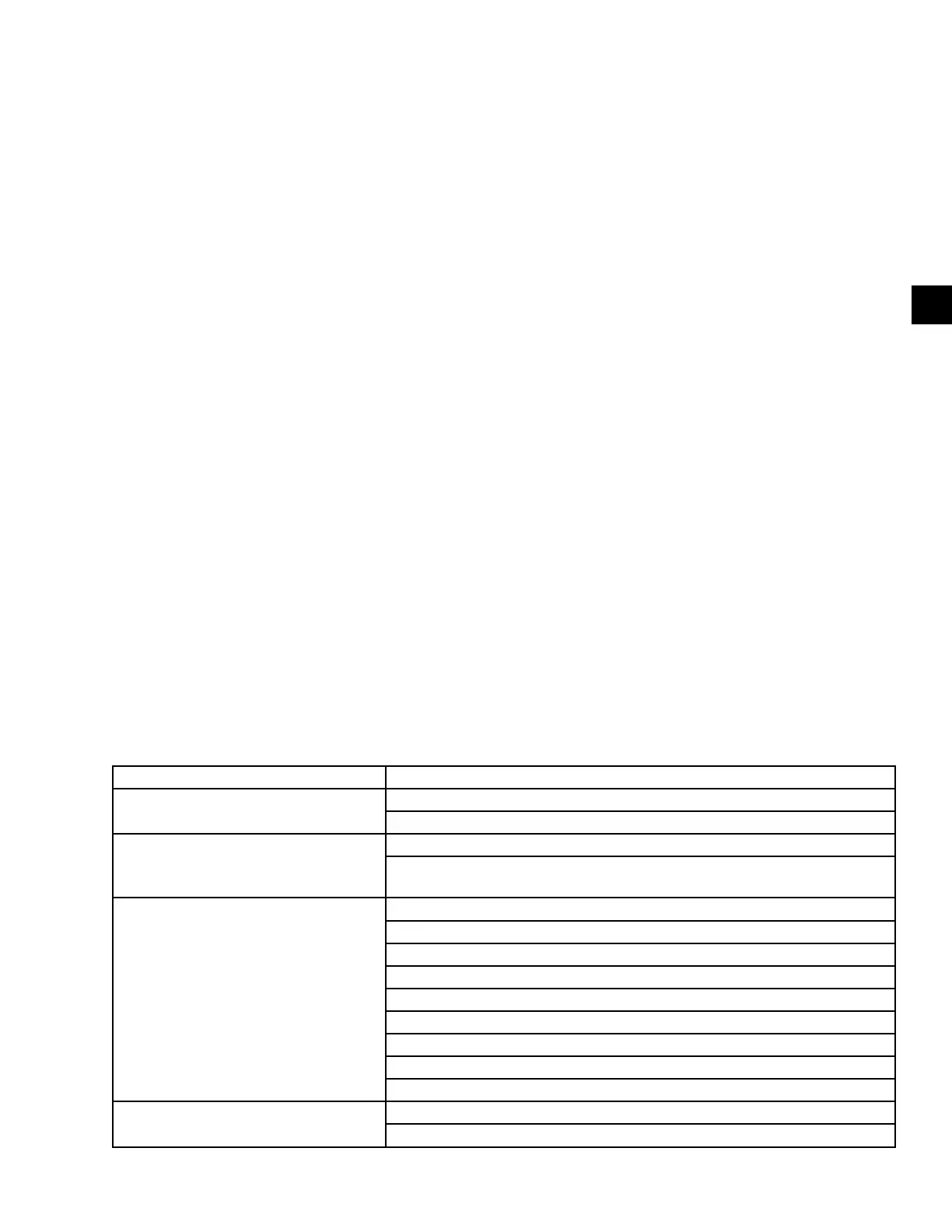
TABLE 21 - SZVAV SUPPLY FAN SPEED
STATUS UNIT MODE
Supply fan at SZVAV minimum speed
Occ Standby (continuous ventilation is User Enabled)
Occ/Unocc Cooling Low
Supply fan speed is modulating up/down
Unit mode switches from Occ/Unocc Cooling Low to Occ/Unocc Cooling High
At this point the supply fan speed starts to increase/decrease as the cooling
demand increases/decreases
Supply fan speed at 100%
Occ Cooling High (see above)
Unocc Cooling High (see Above)
Occ Heating Low
Occ Heating High
Unocc Heating Low
Unocc Heating High
Comfort Vent Cool
Comfort Vent Heat
Morning Warm-Up
Supply fan is OFF
Occ Standby (continuous ventilation is User Disabled)
Unocc Standby