JOHNSON CONTROLS
68
FORM 100.50-NOM12
ISSUE DATE: 04/02/2019
SECTION 5 – SEQUENCE OF OPERATION
5 Volts
0 Volts
Duct Static Pres Rst
Voltage
DSP Setpoint
Active
DUCT STATIC RESET
HIGH SETP
DUCT STATIC RESET
LOW SETP
LD10309A
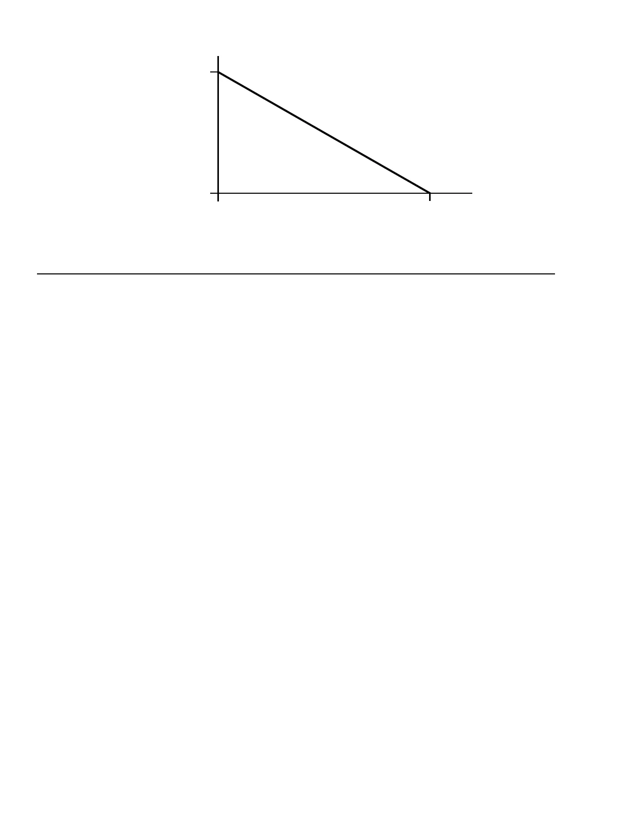
FIGURE 27 - ACTIVE DUCT STATIC PRESSURE SETPOINT VS. DUCT STATIC PRESSURE RESET VOLTAGE
• When duct static reset is User Disabled, the ac-
tive duct static pressure setpoint is always the duct
static reset high setpoint.
• When duct static reset is User Enabled, the active
duct static pressure setpoint is either the duct static
reset high setpoint, duct static reset low setpoint,
or somewhere in between depending on the reset
signal provided to the IPU board.
• The duct static reset high and duct static reset low
setpoints can be found under the SETPOINTS-
SUPPLY SYSTEM menu.
• These setpoints are also available on a BAS.
Duct Static Reset High Setpoint
• This is the active duct static pressure setpoint
that the IPU board tries to maintain when
duct static reset is User Disabled.
• This is the high end of the static pressure
range when duct static reset is User Enabled.
Duct Static Reset Low Setpoint
• This is the low end of the duct static pressure
range when duct static reset is User Enabled.
Duct Static Over Pressure
• This is the duct static pressure that causes the
unit to immediately shut down on a Duct High
Pressure Alarm.
Supply Fan Sync
• Supply fan sync is only applicable for Series 100
units congured as VAV.
• The Series 100 unit has the ability to synchronize
the operation of the supply fans when units of the
same tonnage are installed in a master/satellite ar-
rangement, also known as twinning.
• Supply fan sync allows the BAS to input the same
VDC signal to two or more units. This ensures the
supply fans are running at the same speed.
• The factory strongly recommends installing eld
provided isolation dampers and manual reset duct
static pressure safety switches when operating in
this type of arrangement.
• To utilize this sequence, supply fan sync must be
User Enabled and the unit type must be VAV.
• Find supply fan sync under the PROGRAM-SUP-
PLY SYSTEM menu.
• To utilize this sequence, a 1–5 VDC signal must
be provided to CTB1, terminals 25, 26, and 27:
a. Terminal 25: +5 VDC (duct static pressure
setpoint +5 VDC)
b. Terminal 26: duct static pressure + (duct static
reset +)
c. Terminal 27: duct static pressure - (duct static
reset -)
• The IPU board requires approximately 1 VDC to
start the supply fan. Once the fan is started, Table
25 on page 69 shows the expected speeds and
speed percentage at different VDC signals.
• When the VDC signal drops to approximately 0.5
VDC, the supply fan shuts down on auto reset.
After voltage increases above 1 VDC, the supply
fan restarts.