Table 51: Set the JNP10K-PWR-DC2 DIP Switches
(Connued)
Switch State Descripon
O IP0 is not present.
2 On IP1 is present.
O IP1 is not present.
3 On Enabled for 80-A feed; 2750 W is for a single feed, and 5500 W is for
dual feeds.
O Enabled for 60-A feed; 2200 W is for a single feed, and 4400 W is for
dual feeds.
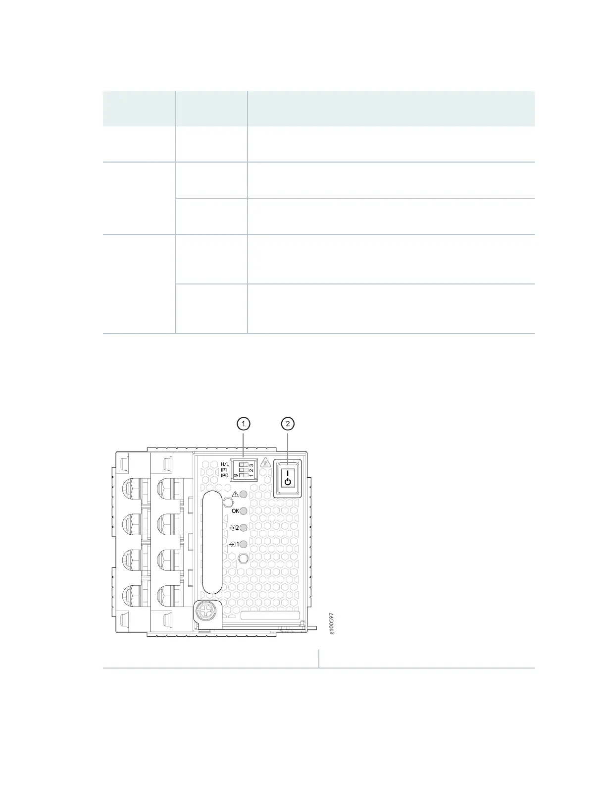
Figure 64: Set the Enable Switches for the Power Source
1
— DIP switches 2— Power switch: on (|) and standby (O)
18. Verify that the input 1 and 2 LEDs on the power supply faceplate are lit and are on steadily.
19. Press the power switch to the on (|) posion.
160