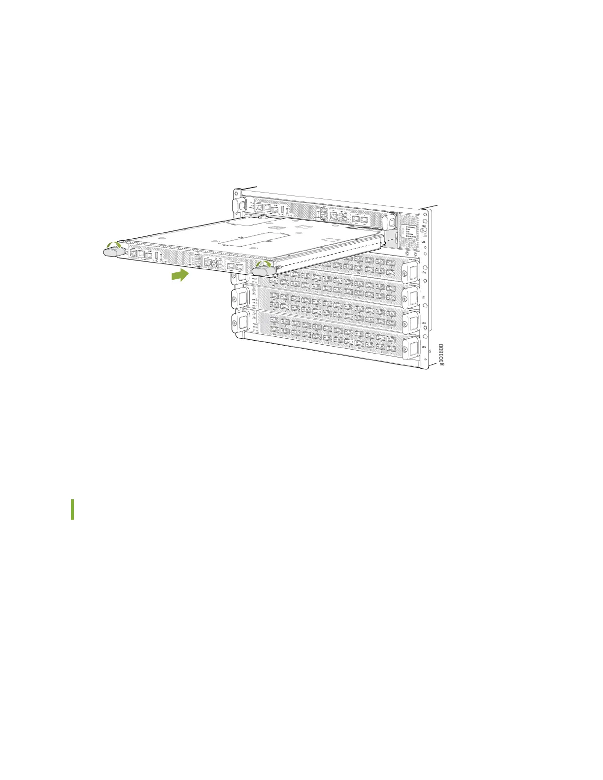
7. Grasp both handles and rotate them clockwise simultaneously unl the RCB is fully seated and the
handles are vercal (see Figure 86 on page 189).
The RCB begins the power-on sequence aer it is fully seated.
Figure 86: Roung and Control Board Installaon
8. To verify that the RCB is funconing normally, check the PWR LED on its faceplate and the
CONTROL BOARDS LED on the status panel. Both LEDs should light steadily shortly aer the RCB is
installed. If the PWR LED is blinking yellow, the available power might be insucient. Ensure that
you have adequate power for the addional unit.
You can also use the show chassis environment cb command to verify that the RCB is online.
Remove an MX10004 Roung and Control Board
A Juniper Networks MX10004 router can have one or two Roung and Control Boards (RCBs),
depending on the conguraon. You can install RCBs in either of the two top slots on the front of the
chassis.
In redundant conguraons, an RCB is a hot-removable and hot-insertable eld-replaceable unit (FRU).
In base conguraons, you need to install a second RCB before removing a failing RCB to prevent the
router from shung down. We recommend that you take base systems oine before replacing the RCB.
Before you remove an RCB, ensure that you have the following items:
• An electrostac discharge (ESD) grounding strap
• An anstac mat
189