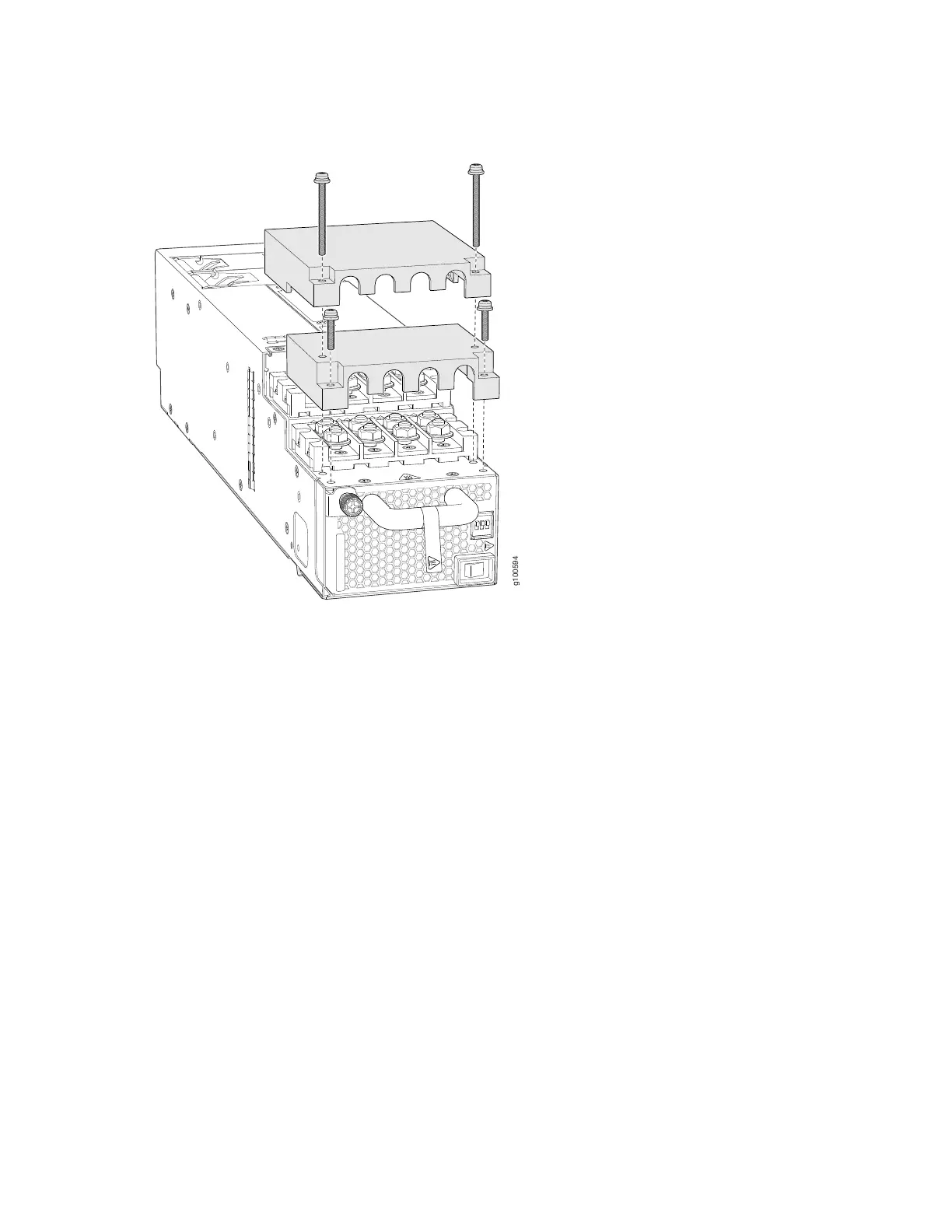
Figure 94: Removing the Plastic Cable Cover on a JNP10K-PWR-DC2 Power Supply
6. Remove the nuts from each DC power input terminal, using the 13/32 in. (10 mm) nut driver or socket
wrench to loosen the nuts.
7. Ensure that the power source circuit breaker is open so that the voltage across the DC power source
cable leads is 0 V and that the cable leads do not become active while you are connecting DC power.
8. Verify that the DC power cables are correctly labeled before making connections to the power supply.
In a typical power distribution scheme where the return is connected to chassis ground at the battery
plant, you can use a multimeter to verify the resistance of the –48V and RTN DC cables to chassis
ground:
•
The cable with very high resistance (indicating an open circuit) to chassis ground is negative (–) and
will be installed on the –48V (input) DC power input terminal.
•
The cable with very low resistance (indicating a closed circuit) to chassis ground is positive (+) and
will be installed on the RTN (return) DC power input terminal.
203